
Escape 2WD V6-3.0L (2009)
cleared using the module on-demand self-test, then the Clear DTC operation on the scan tool (if the on-demand test shows the fault corrected). The
module never resets the fault event counter to zero and continues to advance the fault event counter as short circuit fault events occur.
If the number of short circuit fault events reach the third level, then DTCs B106F and B1342 set along with the associated continuous DTC. This DTC
cannot be cleared and the module must be replaced.
The SJB FET protected output circuits for the stoplamp system are the LH rear stop/turn lamp and the RH rear stop/turn lamp output circuits.
Inspection And Verification
Stoplamps
Inspection and Verification
1. Verify the customer concern.
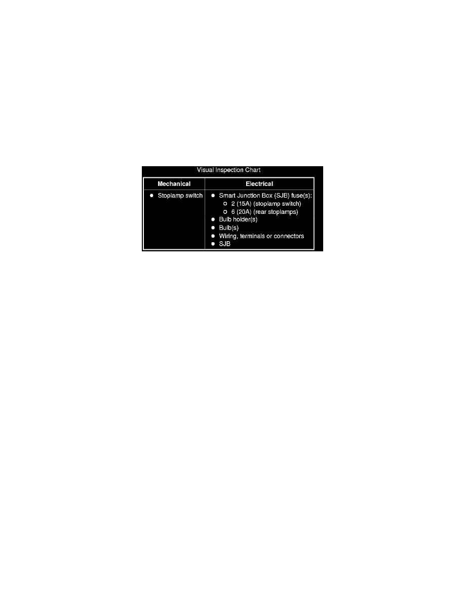
2. Visually inspect for obvious signs of mechanical or electrical damage.
Visual Inspection Chart
3. If an obvious cause for an observed or reported concern is found, correct the cause (if possible) before proceeding to the next step.
4. NOTE: Make sure to use the latest scan tool software release.
If the cause is not visually evident, connect the scan tool to the Data Link Connector (DLC).
5. NOTE: The Vehicle Communication Module (VCM) LED prove-out confirms power and ground from the DLC are provided to the VCM.
If the scan tool does not communicate with the VCM:
-
Check the VCM connection to the vehicle.
-
Check the scan tool connection to the VCM.
-
Refer to Information Bus, No Power To The Scan Tool, to diagnose no power to the scan tool.
6. If the scan tool does not communicate with the vehicle:
-
Verify the ignition key is in the ON position.
-
Verify the scan tool operation with a known good vehicle.
-
Refer to Information Bus to diagnose no response from the PCM.
7. Carry out the network test.
-
If the scan tool responds with no communication for one or more modules, refer to Information Bus.
-
If the network test passes, retrieve and record the continuous memory DTCs.
8. Clear the continuous DTCs and carry out the self-test diagnostics for the SJB.
9. If the DTCs retrieved are related to the concern, refer to Diagnostic Trouble Code (DTC) Chart See: Testing and Inspection. For all other DTCs,
refer to the Diagnostic Trouble Code (DTC) Chart in Body Control Systems. See: Body and Frame/Body Control Systems/Testing and
Inspection/Diagnostic Trouble Code Descriptions/Diagnostic Trouble Code (DTC) Chart
10. If no DTCs related to the concern are retrieved, GO to Symptom Chart. See: Symptom Related Diagnostic Procedures