
Escape 2WD V6-3.0L (2009)
Information Bus: Description and Operation
Communications Network
Vehicle communication utilizes both ISO 9141 and Controller Area Network (CAN) communications. ISO 9141 is used for diagnostic use only while
CAN allows many modules to communicate with each other on a common network. CAN in-vehicle networking is a method for transferring data among
distributed electronic modules via a serial data bus.
Without serial networking, intermodule communication requires dedicated, point to point wiring resulting in bulky, expensive, complex, and difficult to
install wiring harnesses. Applying a serial data network reduces the number of wires, combining the signals on a single network. Information is sent to
the individual control modules that control each function.
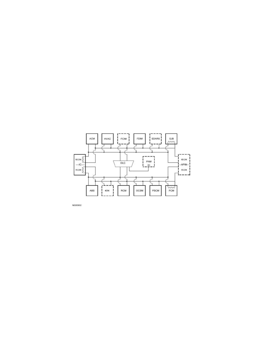
The vehicle has 3 module communication networks:
-
ISO 9141
-
Medium Speed Controller Area Network (MS-CAN)
-
High Speed Controller Area Network (HS-CAN)
All 3 networks are connected to the Data Link Connector (DLC). This makes diagnosis and testing of these systems easier by allowing one scan tool to
be able to diagnose and control any module on the 3 networks from one connector. The DLC can be found under the instrument panel between the
steering column and the Audio Control Module (ACM).
Network Topology