
Escape 2WD V6-3.0L (2009)
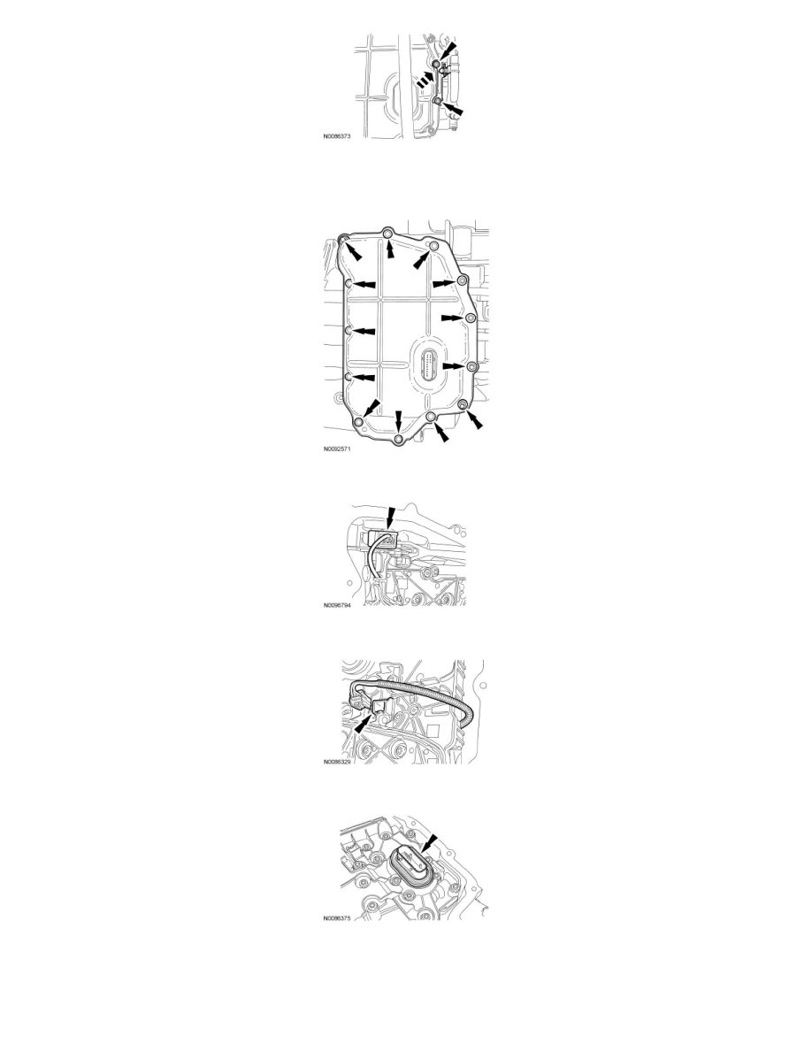
8. NOTE: Note the location of the stud bolts for assembly.
Remove the 8 bolts, 5 stud bolts and the main control cover.
9. Disconnect the Transmission Range (TR) sensor electrical connector.
10. Disconnect the Output Shaft Speed (OSS) sensor electrical connector.
11. Remove the main control cover grommet.
12. NOTICE: The main control should be handled with care, damage to the main control may occur.
NOTE: Note the location of the different length bolts for assembly.
Remove the nut, 22 bolts and the main control.