
Escape 2WD V6-3.0L (2009)
3. NOTE: Make sure that the manual lever pin (part of the TR sensor) is correctly installed in the manual valve.
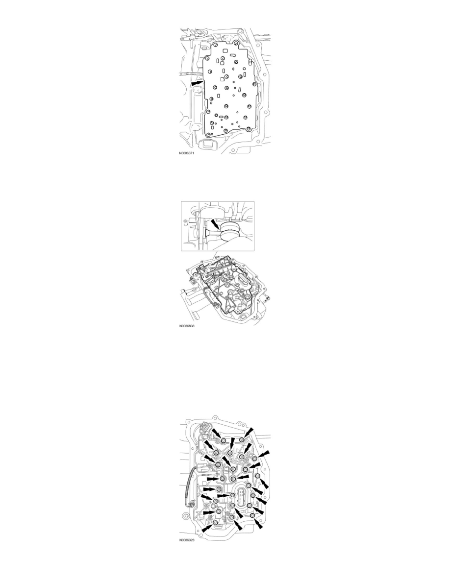
Install the main control.
4. NOTICE: Make sure not to pinch the Output Shaft Speed (OSS) or Transmission Range (TR) sensor wiring harnesses when installing the
main control.
NOTE: Install the different length bolts in the locations noted during disassembly.
Install the main control and the nut and 22 bolts.
-
Tighten to 10 Nm (89 lb-in).
5. Route the OSS sensor wiring harness and connect the electrical connector.