
Escape 4WD L4-2.3L VIN H Hybrid (2005)
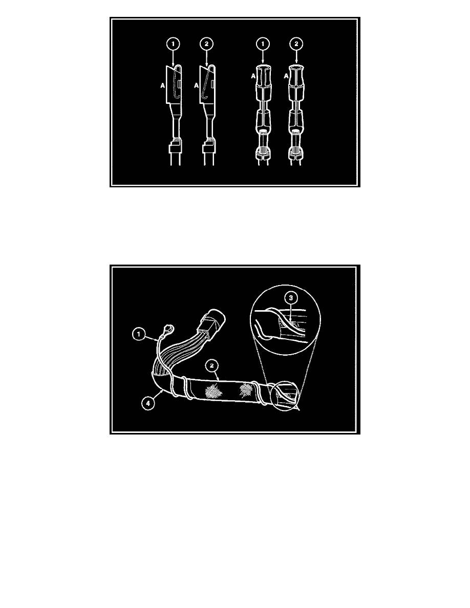
1
=
Enlarged
2
=
Normal
Any probe entering the terminal may enlarge the contact spring opening creating an intermittent signal. Insert the correct mating terminal (Location A_
from the service kit and feel for a loose fit.
Electrical short inside the harness
1
=
Solder coated wire to ground
2
=
Harness protective tape
3
=
Intermittent short
Solder coated wire pierced through the insulation of another circuit
4
=
Grounding foil
Electrical short within the harness