
Escape 4WD L4-2.5L (2010)
Removal and Installation
1. With vehicle in NEUTRAL, position it on a hoist. For additional information, refer to Vehicle Jacking and Lifting.
2. Remove the fuel rail. For additional information, refer to Fuel Delivery and Air Induction.
3. Disconnect the vacuum supply hose.
-
Depress the quick release locking ring.
-
Pull the vacuum hose out of the quick release fitting.
4. Disconnect the fuel vapor return hose from the intake manifold.
5. Disconnect the Manifold Absolute Pressure (MAP) electrical connector.
6. Disconnect the Evaporative Emission (EVAP) canister purge valve electrical connector.
7. Disconnect the electronic throttle control electrical connector.
8. Disconnect the Knock Sensor (KS) electrical connector.
-
Detach the wire harness pin-type retainer.
9. Detach the heater hose pin-type retainer.
10. Detach all wiring harness pin-type retainers from the intake manifold and position the wiring harness aside.
11. Loosen the clamp and disconnect Air Cleaner (ACL) outlet pipe from the Throttle Body (TB).
-
To install, tighten to 4 Nm (35 lb-in).
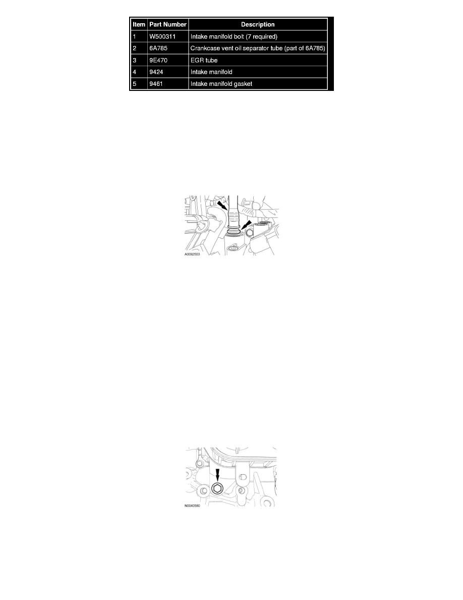
12. Remove the intake manifold lower bolt.
-
To install, tighten to 18 Nm (159 lb-in).
13. Remove the 6 bolts and position the intake manifold aside to access the crankcase vent oil separator tube and the EGR tube.
-
To install, tighten to 18 Nm (159 lb-in).
14. Squeeze the 2 crankcase vent oil separator tube tabs and disconnect the tube from the intake manifold.
15. Remove the EGR tube.
-
To install, tighten to 55 Nm (41 lb-ft).