
Escape 4WD L4-2.5L (2010)
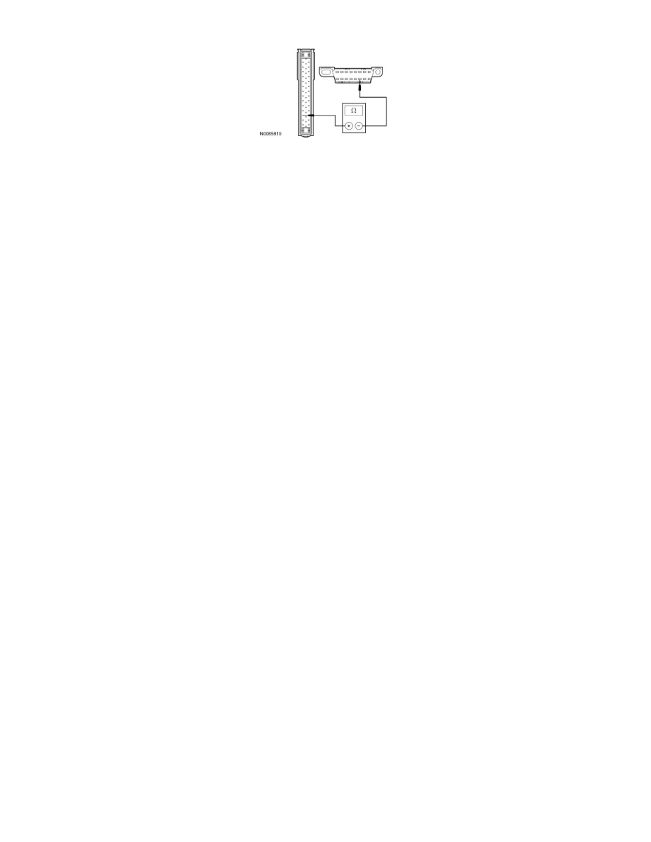
harness side.
-
Are the resistances less than 5 ohms?
Yes
CONNECT the negative battery cable. GO to B4.
No
REPAIR the circuit in question. CONNECT the negative battery cable. CLEAR the DTCs. REPEAT the network test with the scan tool.
-------------------------------------------------
B4 CARRY OUT A VOLTAGE DROP TEST ON THE VOLTAGE SUPPLY CIRCUIT
-
Ignition OFF.
-
Disconnect: Engine Cooling Fan C1074.
-
Connect one fused jumper wire between the ABS module C155-1, circuit SBB09 (RD), harness side and the engine cooling fan C1074 pin 1,
component side.
-
Connect the second fused jumper wire between the engine cooling fan C1074 pin 3, component side and the battery negative post.
-
NOTE: Be sure that there is some voltage drop when carrying out this step. There should always be some voltage drop on all circuits. A voltage
reading of 0 volts indicates that the test is being incorrectly carried out.
-
Measure the voltage between the BJB fuse 9 (50A) and the ABS module C155-1, circuit SBB09 (RD), harness side.
-
Is the voltage less than 0.4 volt?
Yes
For Escape and Mariner, GO to B6.
For Hybrid, GO to B5.
No
REPAIR circuit SBP09 (RD) for high resistance. TEST the system for normal operation.
-------------------------------------------------
B5 TEST THE HOT AT ALL TIMES B+ VOLTAGE INPUT CIRCUIT FOR VOLTAGE
-
Connect one fused jumper wire between the ABS module C155-32, circuit SBB18 (YE/RD), harness side and the engine cooling fan C1074 pin 1,
component side.
-
Connect the second fused jumper wire between the engine cooling fan C1074 pin 3, component side and the battery negative post.
-
NOTE: Be sure that there is some voltage drop when carrying out this step. There should always be some voltage drop on all circuits. A voltage
reading of 0 volts indicates that the test is being incorrectly carried out.
-
Measure the voltage between the BJB fuse 18 (50A) and the ABS module C155-32, circuit SBB18 (YE/RD), harness side.
-
Is the voltage less than 0.4 volt?
Yes
GO to B6.
No
REPAIR circuit SBP18 (YE/RD) for high resistance. TEST the system for normal operation.