
Escape 4WD L4-2.5L (2010)
-
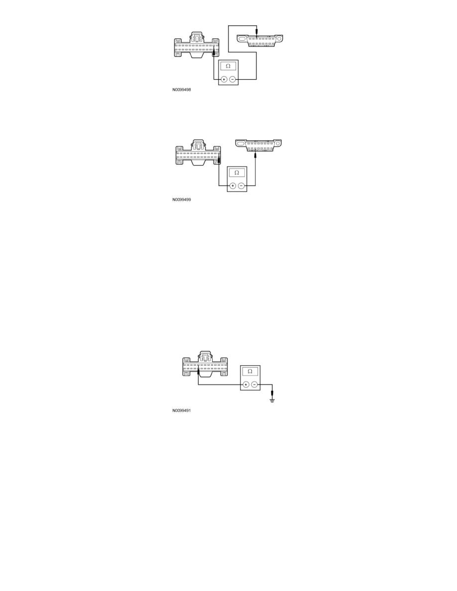
Measure the resistance between the IC C220-1, circuit VDB07 (VT/OG), harness side and the DLC C251-11, circuit VDB07 (VT/OG), harness
side.
-
Are the resistances less than 5 ohms?
Yes
CONNECT the negative battery cable. GO to C7.
No
REPAIR the circuit in question. CONNECT the negative battery cable. CLEAR the DTCs. REPEAT the network test with the scan tool.
-------------------------------------------------
C5 CHECK THE IC GROUND CIRCUIT FOR AN OPEN
-
Measure the resistance between the IC C220-9, circuit GD112 (BK/GN), harness side and ground.
-
Is the resistance less than 5 ohms?
Yes
CONNECT the negative battery cable. GO to C6.
No
REPAIR the circuit. CONNECT the negative battery cable. CLEAR the DTCs. REPEAT the network test with the scan tool.
-------------------------------------------------
C6 CHECK THE IC VOLTAGE SUPPLY CIRCUITS FOR AN OPEN
-
Disconnect: IC C220 .
-
Ignition ON.
-
Measure the voltage between the IC C220-19, circuit SBP26 (YE/RD), harness side and ground; and between the IC C220-20, circuit CBP29
(WH/VT), harness side and ground.