
Escape 4WD L4-2.5L (2010)
-
Ignition OFF.
-
Disconnect: Negative Battery Cable .
-
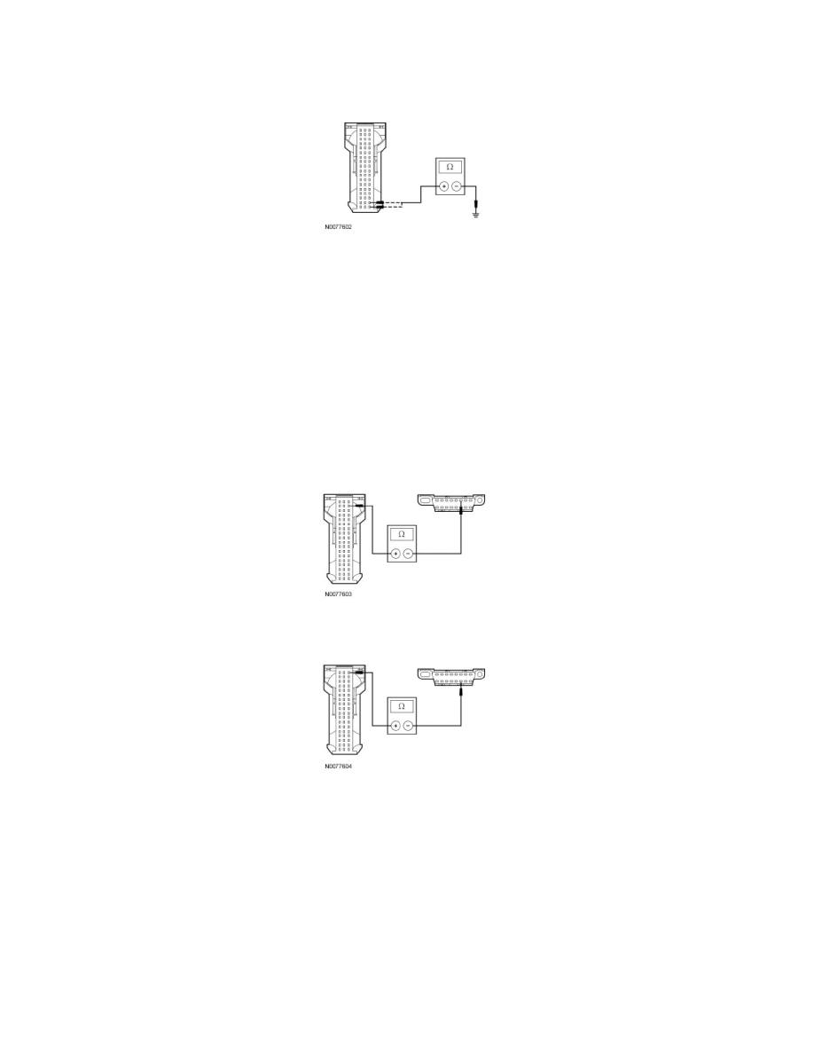
Measure the resistance between the APIM C3338-37, circuit GD115 (BK/GY), harness side and ground; and between the APIM C3338-38, circuit
GD115 (BK/GY), harness side and ground.
-
Are the resistances less than 5 ohms?
Yes
GO to R3.
No
REPAIR the circuit. CONNECT the negative battery cable. CLEAR the DTCs. REPEAT the network test with the scan tool.
-------------------------------------------------
R3 CHECK THE HS-CAN CIRCUITS BETWEEN THE APIM AND THE DLC FOR AN OPEN
-
Measure the resistance between the APIM C3338-53, circuit VDB04 (WH/BU), harness side and the Data Link Connector (DLC) C251-6, circuit
VDB04 (WH/BU), harness side.
-
Measure the resistance between the APIM C3338-54, circuit VDB05 (WH), harness side and the DLC C251-14, circuit VDB05 (WH), harness
side.
-
Are the resistances less than 5 ohms?
Yes
GO to R4.
No
REPAIR the circuit in question. CONNECT the negative battery cable. CLEAR the DTCs. REPEAT the network test with the scan tool.
-------------------------------------------------
R4 CHECK THE MS-CAN CIRCUITS BETWEEN THE APIM AND THE DLC FOR AN OPEN
-
Measure the resistance between the APIM C3338-16, circuit VDB06 (GY/OG), harness side and the DLC C251-3, circuit VDB06 (GY/OG),
harness side.