
Escape 4WD L4-2.5L (2010)
-
Are the resistances greater than 1,000 ohms?
Yes
CONNECT the negative battery cable. GO to T43.
No
For hybrid, GO to T32.
For non-hybrid, REPAIR the circuit. CONNECT all modules. CONNECT the negative battery cable. CLEAR the DTCs. REPEAT the network test with
the scan tool.
-------------------------------------------------
T32 CHECK THE HS-CAN (+) AND HS-CAN (-) CIRCUITS FOR A SHORT TO GROUND WITH THE TCM DISCONNECTED
-
Disconnect: TCM C1458a .
-
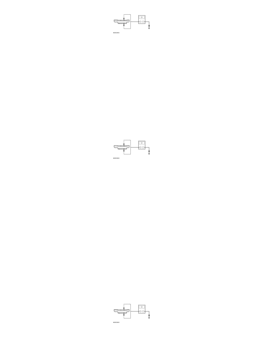
Measure the resistance between the DLC C251-6, circuit VDB04 (WH/BU), harness side and ground; and between the DLC C251-14, circuit
VDB05 (WH), harness side and ground.
-
Are the resistances greater than 1,000 ohms?
Yes
CONNECT the negative battery cable. GO to T44.
No
GO to T33.
-------------------------------------------------
T33 CHECK THE HS-CAN (+) AND HS-CAN (-) CIRCUITS FOR A SHORT TO GROUND WITH THE BCM DISCONNECTED
WARNING: To prevent the risk of high-voltage shock, always follow precisely all warnings and service instructions, including instructions to
depower the system. The high-voltage hybrid system utilizes approximately 300 volts DC, provided through high-voltage cables to its
components and modules. The high-voltage cables and wiring are identified by orange harness tape or orange wire covering. All high-voltage
components are marked with high-voltage warning labels with a high-voltage symbol. Failure to follow these instructions may result in serious
personal injury or death.
WARNING: Always wear high-voltage insulated safety gloves with leather outer gloves and a face shield when servicing the battery pack
sensor module (BPSM) and never remove the high-voltage BPSM connector unless directed by a service procedure. High voltage is present at
the BPSM at all times, even with service disconnect plug removal. Depowering the system will not remove voltage from the BPSM connector
with the orange harness. Follow all service instructions. Failure to follow these instructions may result in serious personal injury or death.
-
Disconnect: BCM C4227a .
-
Measure the resistance between the DLC C251-6, circuit VDB04 (WH/BU), harness side and the DLC C251-14, circuit VDB05 (WH), harness
side.