
Escape 4WD L4-2.5L Hybrid (2009)
-
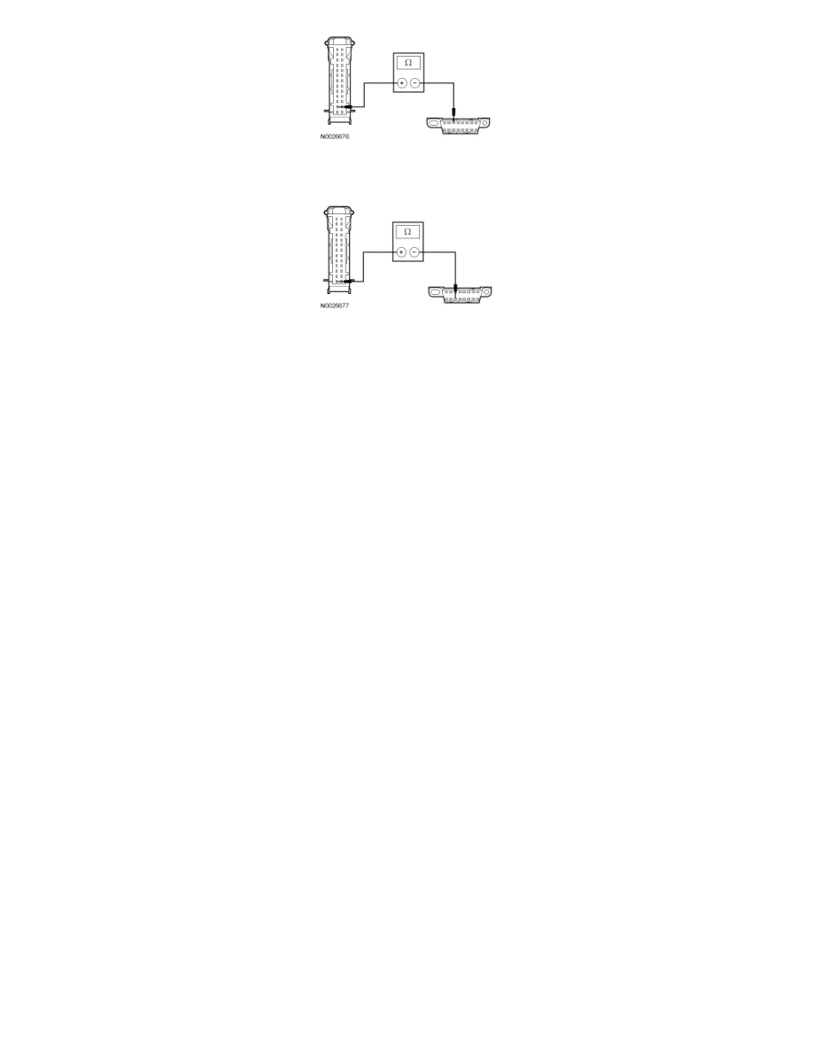
Measure the resistance between the IC C220-1, circuit VDB07 (VT/OG), harness side and the DLC C251-11, circuit VDB07 (VT/OG), harness
side.
-
Are the resistances less than 5 ohms?
Yes
GO to D6.
No
REPAIR the circuit in question. CLEAR the DTCs. REPEAT the network test with the scan tool.
-------------------------------------------------
D6 CHECK FOR CORRECT IC OPERATION
-
Disconnect the IC connector.
-
Check for:
-
corrosion
-
damaged pins
-
pushed-out pins
-
Connect the IC connector and make sure it seats correctly.
-
Operate the system and verify the concern is still present.
-
Is the concern still present?
Yes
INSTALL a new IC. CLEAR the DTCs. REPEAT the network test with the scan tool.
No
The system is operating correctly at this time. The concern may have been caused by a loose or corroded connector. CLEAR the DTCs. REPEAT the
network test with the scan tool.
-------------------------------------------------
Pinpoint Test E: The Restraints Control Module (RCM) Does Not Respond To The Scan Tool
Communications Network
Pinpoint Tests
Pinpoint Test E: The Restraints Control Module (RCM) Does Not Respond To The Scan Tool
Refer to Wiring Diagram Set 14 (Escape/Mariner, Escape Hybrid/Mariner Hybrid), Module Communications Network for schematic and connector
information. See: Diagrams/Electrical Diagrams/Diagrams By Number
Refer to Wiring Diagram Set 46 (Escape/Mariner, Escape Hybrid/Mariner Hybrid), Supplemental Restraint Systems for schematic and connector
information. See: Diagrams/Electrical Diagrams/Diagrams By Number