
Escape 4WD V6-181 3.0L DOHC VIN 1 Duratec (2003)
Information Bus: Testing and Inspection
Module Configuration
Initial Inspection
INSPECTION AND VERIFICATION
1. Visually inspect for obvious signs of electrical damage.
VISUAL INSPECTION CHART
Electrical
-
Damaged wiring harness
-
Loose or corroded connectors
-
Instrument cluster (IC)
-
Generic electronic module (GEM)
-
Powertrain control module (PCM)
2. If the concern remains after inspection, connect the diagnostic tool to the data link connector (DLC) located beneath the instrument panel and
select the vehicle to be tested from the diagnostic tool menu. If the diagnostic tool does not communicate with the vehicle:
-
check that the program card is correctly installed.
-
check the connections to the vehicle.
-
check that the ignition switch is in the RUN position.
3. If the diagnostic tool still does not communicate with the vehicle, refer to Module Communications Network (Information Bus).
4. Refer to the Symptom Chart. See: Diagnosis By Symptom
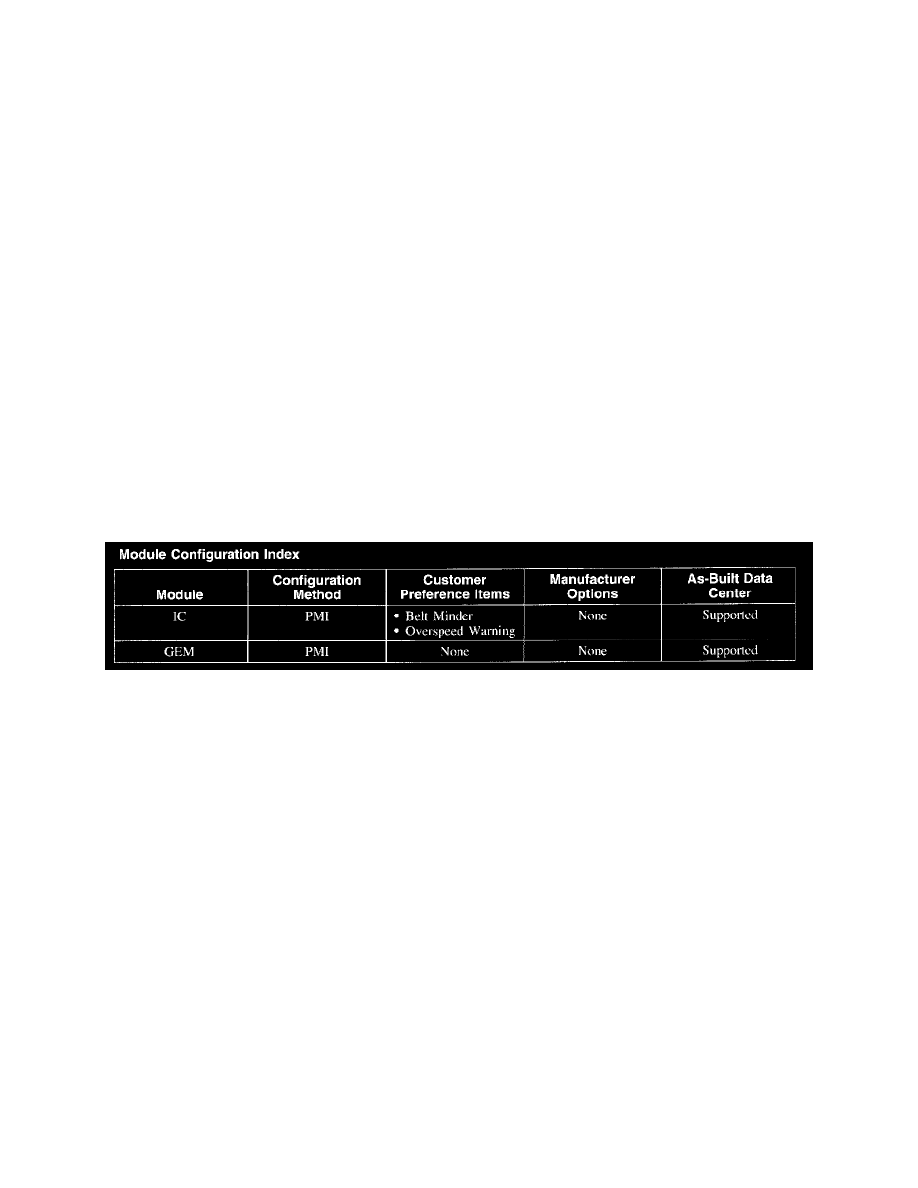
Module Configuration Index
MODULE CONFIGURATION INDEX
Module Configuration Index
NOTE: Do not contact the As-Built Data Center unless the diagnostic tool instructs you to do so. The diagnostic tool will not allow you to use as-built
data information unless the diagnostic tool first prompts you for the As-Built Data Center information.