
Escape 4WD V6-181 3.0L DOHC VIN 1 Duratec (2003)
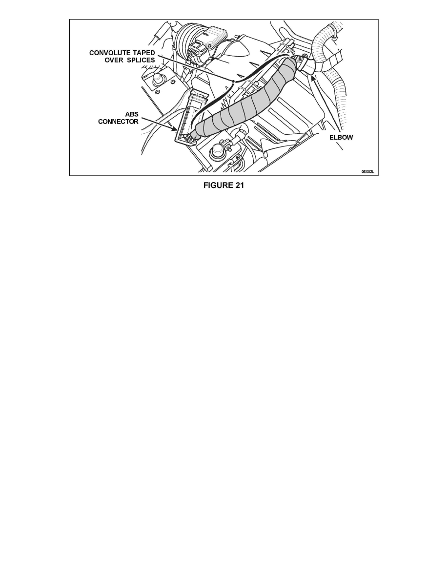
7. Install the supplied convolute tubing over the spliced area and secure with electrical tape. Apply tape to the entire length of the convolute and be sure
to secure the convolute to the elbow at one end, and as close as possible to the ABS connector on the other. See Figure 21.
8. Install a new ABS module. Perform Labor Operation F - Install New ABS Module and Apply Electrical Grease.
9. Reconnect the battery negative terminal.
10. Turn the ignition key to the RUN position. Allow the ABS to carry out a self-test (indicated by illuminating the yellow ABS warning indicator in the
instrument cluster for approximately 3 seconds).
^
If the yellow ABS indicator is not illuminated after 3 seconds, release the vehicle.
^
If the yellow ABS warning indicator stays illuminated after the self-test, contact the Special Support Service Center.
LABOR OPERATION F - INSTALL NEW ABS MODULE AND APPLY ELECTRICAL GREASE
NOTE:
Module configuration or reprogramming is not required when installing a new ABS module.
1. Disconnect the 2-wire electrical connector at the ABS module.
2. Raise the vehicle on a hoist.
3. Remove the screws and the ABS module.
4. Position the new module and install the screws. Tighten the screws no more than 2 Nm (18 lb-in).
5. Lower the hoist.
6. Apply Motorcraft Electrical Grease XG-1 2 to the ABS module connector, position and connect the harness as follows: