
Escape 4WD V6-181 3.0L DOHC VIN 1 Duratec (2003)
be deactivated.
^
Restraint system diagnostic tool MUST be installed under the seats in the side airbag and safety belt pretensioner (if equipped) to floor connectors.
^
Diagnostics or repairs are not to be performed on a side airbag system and/or a safety belt pretensioner (if equipped) system with the seats in the
vehicle. Prior to attempting to diagnose/repair the side airbag system and/or a safety belt pretensioner (if equipped) system the seats must be
removed from the vehicle and the restraint system diagnostic tools must be installed in the side airbag and the safety belt pretensioner (if equipped)
connectors at the floor connectors. The restraint system diagnostic tools must be removed prior to operating the vehicle over the road.
^
Diagnostics may be performed on seat Systems other than the side airbag or the safety belt pretensioner (if equipped) system (lumbar, climate
controlled, heated, power seat track) with the seat installed in the vehicle as long as the restraint system diagnostic tools are installed under the
seats in the side airbag and safety belt pretensioner to floor connectors.
^
After diagnosing/repairing a seat system the restraint system diagnostic tools must be removed before operating the vehicle over the road.
^
Repair is made by installing a new part only. If the new part does not correct the condition, install the original part and perform the diagnostic
procedure again.
All vehicles
1. Make sure the wheels are in the straight-ahead position.
2. Disconnect the battery ground cable and wait at least one minute.
3. Remove the steering wheel.
WARNING: TO REDUCE THE RISK OF SERIOUS PERSONAL INJURY, READ AND FOLLOW ALL WARNINGS, CAUTIONS,
NOTES, AND INSTRUCTIONS IN THE STEERING WHEEL REMOVAL AND INSTALLATION PROCEDURE.
Vehicles with tilt column
4. Position the steering column completely downward.
All vehicles
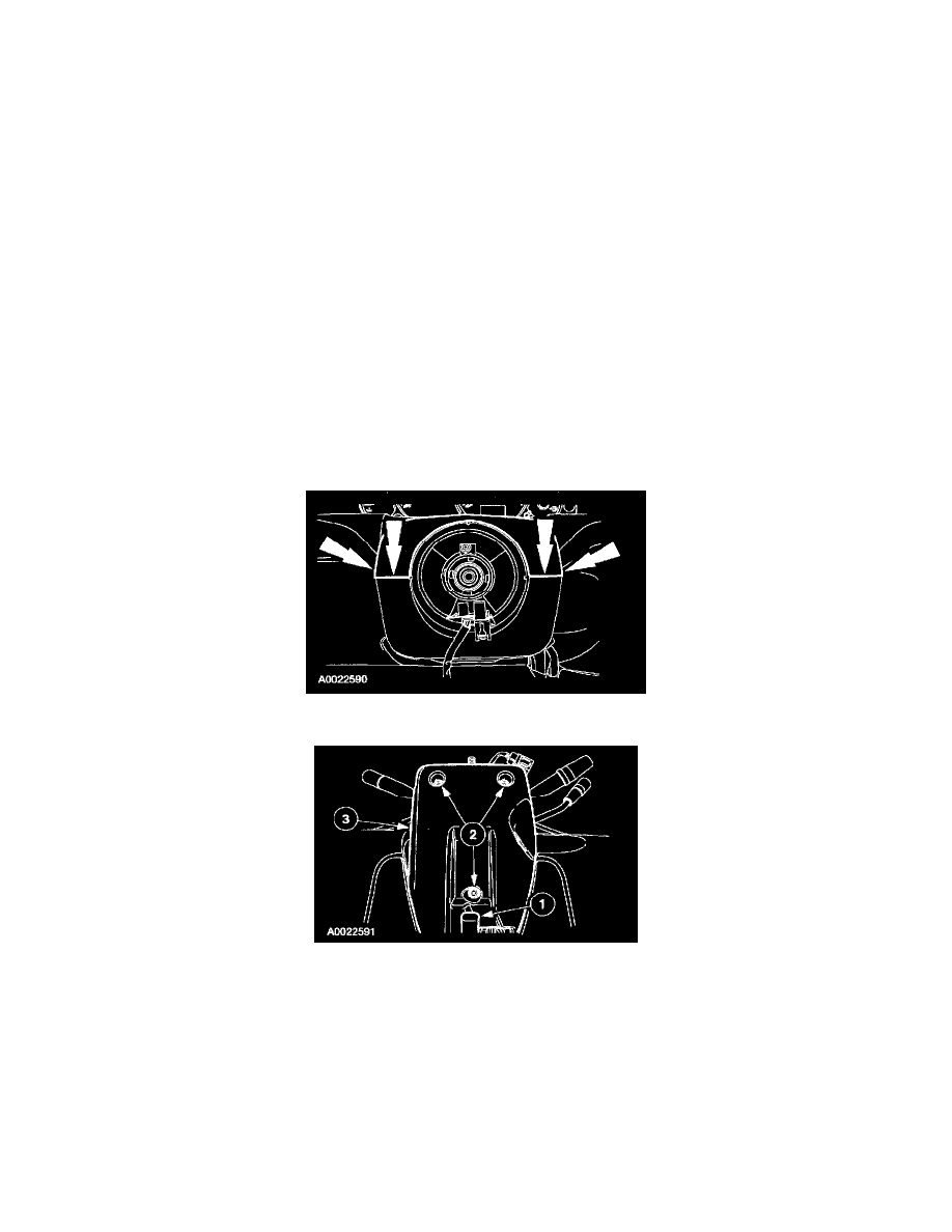
5. Push in where indicated, releasing the retaining tabs, and remove the upper steering column shroud.
6. Remove the lower steering column shroud.
1
Release the tilt column locking lever, if equipped.
2
Remove the three screws.
3
Remove the lower steering column shroud.
NOTE: The steering column must be in the raised position, with the tilt column lever released (if equipped), to remove the lower steering
column shroud.