
Escape 4WD V6-3.0L (2008)
Brake Lamp: Initial Inspection and Diagnostic Overview
Inspection and Verification
INSPECTION AND VERIFICATION
1. Verify the customer concern.
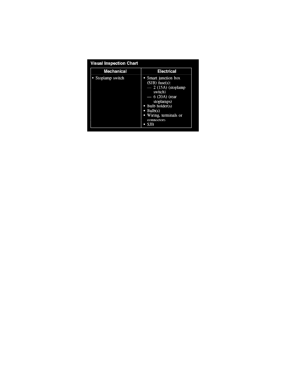
2. Visually inspect for obvious signs of mechanical or electrical damage.
Visual Inspection Chart
3. If an obvious cause for an observed or reported concern is found, correct the cause (if possible) before proceeding to the next step.
NOTE:
-
Make sure the headlamp switch is in the OFF position.
-
Make sure the multifunction switch is in the LOW BEAM position.
4. NOTE: Make sure to use the latest scan tool software release.
If the cause is not visually evident, connect the scan tool to the data link connector (DLC).
5. NOTE: The vehicle communication module (VCM) LED prove-out confirms power and ground from the DLC are provided to the VCM.
If the scan tool does not communicate with the VCM:
-
Check the VCM connection to the vehicle.
-
Check the scan tool connection to the VCM.
-
Refer to Information Bus (Module Communications Network), No Power To The Scan Tool, to diagnose no communication with the scan tool.
6. If the scan tool does not communicate with the vehicle:
-
Verify the ignition key is in the ON position.
-
Verify the scan tool operation with a known good vehicle.
-
Refer to Information Bus (Module Communications Network) to diagnose no response from the powertrain control module (PCM).
7. Carry out the network test.
-
If the scan tool responds with no communication for one or more modules, refer to Information Bus (Module Communications Network).
-
If the network test passes, retrieve and record the continuous memory DTCs.
8. Clear the continuous DTCs and carry out the self-test diagnostics for the smart junction box (SJB).
9. If the DTCs retrieved are related to the concern, go to DTC Charts. For all other DTCs, refer to Body Control Systems (Multifunction Electronic
Control Module). See: Diagnostic Trouble Code Descriptions
10. If no DTCs related to the concern are retrieved, GO to Symptom Chart. See: Symptom Related Diagnostic Procedures
Principles of Operation
PRINCIPLES OF OPERATION
The smart junction box (SJB) monitors the input from the stoplamp switch. When the brake pedal is applied, voltage is routed to the SJB and the high
mounted stoplamp. The SJB then supplies voltage to the stoplamps.
Field-Effect Transistor (FET) Protection
The SJB utilizes a FET protective circuit strategy for many of its outputs (for example, the headlamp output circuit). Output loads (current level) are
monitored for excessive current (typically short circuits) and are shut down (turns off the voltage or ground provided by the module) when a fault is