
Escape 4WD V6-3.0L (2008)
6. If the DTCs retrieved are related to the concern, go to DTC Charts. Follow the non-network DTC diagnostics (B-codes, C-codes, P-codes) prior to
the network DTC diagnostics (U-codes). For all other DTCs, refer to Body Control Systems (Multifunction Electronic Control Module). See:
Diagnostic Trouble Code Descriptions/Module Communications Network
7. If no DTCs related to the concern are retrieved, GO to Symptom Chart. See: Symptom Related Diagnostic Procedures
Principles of Operation
PRINCIPLES OF OPERATION
Vehicle communication utilizes both International Standards Organization (ISO) 9141 and controller area network (CAN) communications. ISO 9141 is
used for diagnostic use only, and CAN is a method for transferring data among distributed electronic modules via a serial data bus.
The vehicle is equipped with 3 module communication networks:
-
ISO 9141
-
Medium speed (MS) CAN
-
High speed (HS) CAN
ISO 9141 Communications Network
The ISO 9141 communications network is a single wire network. The ISO communications network does not permit intermodule communication and
is only used for the parking aid module. When the scan tool communicates with the parking aid module, the scan tool must request all information, the
module cannot initiate communications.
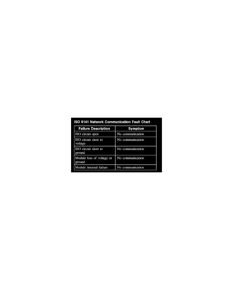
The ISO network operates at a maximum data transfer speed of 10 Kbps for bus messages and is designed for scan tool to module diagnostic use only.
The following fault chart describes the specific ISO 9141 network failures and their resulting symptom:
ISO 9141 Network Communication Fault Chart
MS-CAN
The MS-CAN network uses an unshielded twisted pair cable of data (+) and data (-) circuits. The data (+) and the data (-) circuits are each regulated to
approximately 2.5 volts during neutral or rested network traffic. As bus messages are sent on the data (+) circuit, voltage is increased by
approximately 1.0 volt. Inversely, the data (-) circuit is reduced by approximately 1.0 volt when a bus message is sent. Multiple bus messages can be
sent over the CAN circuits allowing multiple modules to communicate with each other. The MS-CAN is used for the instrument cluster, the front
control interface module (FCIM), the front display interface module (FDIM), electronic automatic temperature control (EATC) or electronic manual
temperature control (EMTC) module, the audio unit, the satellite radio receiver and the smart junction box (SJB) communications, and is designed for
general information transfer. The MS-CAN network will not communicate while certain faults are present, but will operate with diminished
performance with other faults present. The MS-CAN bus may remain operational when 1 of the 2 termination resistors are not present.
The MS-CAN network operates at a maximum data transfer speed of 125 Kbps for bus messages and is designed for general information transfer. The
network will remain operational, but at a degraded level when certain circuit faults are present.
The following fault chart describes the specific MS-CAN network failures and their resulting symptom: