
Escape 4WD V6-3.0L VIN 1 (2005)
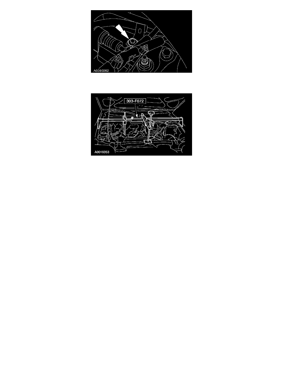
6. Remove the power steering hose bracket bolt.
-
To install, tighten to 10 Nm (89 lb-in).
7. Using the special tool, support the engine.
8. Remove the bolts and the lateral support crossmember.
-
To install, tighten to 115 Nm (85 lb-ft).
9. Remove the splash shield bolt.
10. Remove the front insulator bolt.
-
To install, tighten to 115 Nm (85 lb-ft).
11. Remove the 2 engine support crossmember bolts.
-
To install, tighten to 90 Nm (66 lb-ft).
12. Remove the nut and the engine support crossmember.
-
To install, tighten to 175 Nm (129 lb-ft).
13. Remove the 2 lower control arm ball joint pinch bolt and nuts.
-
To install, tighten to 70 Nm (52 lb-ft).
14. Remove the 2 nuts and disconnect the 2 stabilizer bar links.
-
To install, tighten to 47 Nm (35 lb-ft).
15. Remove the 2 steering gear bolts.
-
To install, tighten to 115 Nm (85 lb-ft).
16. Position the steering gear out of the subframe mounts.
17. Remove the exhaust flexible pipe (2.3L) or the dual converter Y-pipe (3.0L).
18. If equipped with 4WD, remove the driveshaft.
19. NOTE: The engine must be lowered to allow the front subframe to clear the transaxle companion flange.
If equipped with 4WD, use the special tool to lower the rear of the engine approximately 150 mm (5.9 in).
20. NOTE:
-
Do not allow the front subframe rear bolts to come out of the lower control arm bushing.
-
When installing the front subframe rear bolts, make sure both of the front subframe rear bolts are fully engaged in their cage nuts before
tightening to specification.
Loosen the 2 front subframe rear bolts.