
Escape 4WD V6-3.0L VIN 1 (2005)
Horn: Initial Inspection and Diagnostic Overview
Principles of Operation
PRINCIPLES OF OPERATION
The horn relay B+ power and the horn relay switched power are supplied through circuit 1682 (RD/LB). The horn relay is controlled by the horn switch.
The horn relay is grounded through the horn switch by circuit 6 (YE/LG). When the horn switch is pressed, the horn relay control circuit 6 (YE/LG) is
grounded. The relay is then closed causing B+ voltage to be applied to circuit 1 (DB), sounding the horns.
The horn relay is powered on both the control and controlled sides by circuit 1682 (RD/LB). When the horn switch is pressed, the horn relay control
circuit 6 (YE/LG) is grounded through the horn switch. The horn relay is then energized, allowing battery voltage to flow through the horn relay to each
horn through circuit 1 (DB), enabling the horns to sound. When the vehicle security system is armed, the smart junction box (SJB) provides a momentary
ground to the horn relay control side to indicate the system is armed, and a continuous ground when an intrusion is detected.
Inspection and Verification
INSPECTION AND VERIFICATION
1. Verify the customer concern.
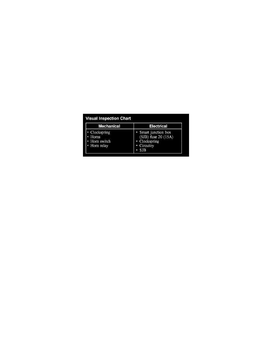
Visual Inspection Chart
2. Visually inspect for obvious signs of mechanical or electrical damage.
3. If an obvious cause for an observed or reported concern is found, correct the cause (if possible) before proceeding to the next step.
4. If the cause is not visually evident, connect the diagnostic tool to the data link connector (DLC) and select the vehicle to be tested from the
diagnostic tool menu. If the diagnostic tool does not communicate with the vehicle:
-
check that the program card is correctly installed.
-
check the connections to the vehicle.
-
check the ignition switch position.
5. If diagnostic tool still does not communicate with the vehicle, refer to the diagnostic tool operating manual.
6. Carry out the diagnostic tool data link test. If the diagnostic tool responds with:
-
CAN or ISO circuit fault; all electronic control units no response/not equipped, refer to Information Bus (Module Communications Network).
-
No response/not equipped for the SJB, go to Body Control Systems (Multifunction Electronic Control Module).
-
System passed, retrieve and record the continuous diagnostic trouble codes (DTCs), erase the continuous DTCs, and carry out self-test
diagnostics for the SJB.
7. If no DTCs related to the concern are retrieved, GO to Symptom Chart to continue diagnosis. See: Symptom Related Diagnostic Procedures