
Escort L4-110 1.8L DOHC (1994)
7.
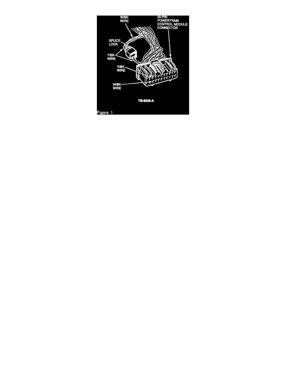
Remove the remaining W/BK wire and terminal from the connector and discard, Figure 2.
8.
Re-tape harness branch using new electrical tape.
9.
Reconnect 22-pin connector to the PCM.
10.
Reinstall control box side cover, shift console and parking brake console. Refer to the 1994 Escort/Tracer Service Manual, pages 01-12-5 and
01-12-6.
11.
Reconnect battery ground cable.
12.
With engine running, measure voltage between STO terminal at the DLC and chassis ground. Voltage should be 12-14 volts.
PART NUMBER
PART NAME
CLASS
(Obtain Locally)
Splice Lock Connector
A
(Scotchlock Or Equivalent)
OTHER APPLICABLE ARTICLES: NONE
WARRANTY STATUS:
Eligible Under The Provisions Of Bumper To Bumper Warranty Coverage
OPERATION DESCRIPTION
TIME
940905A
Cut And Splice Wires
0.4 Hr.
DEALER CODING
BASIC PART NO.
CONDITION CODE
14401
28
OASIS CODES: 203000