
Escort L4-110 1.8L DOHC (1994)
Temperature Sensor (Gauge): Testing and Inspection
1. Remove water temperature indicator sender unit.
2. Place sender in water and heat to 176°F.
3. Measure resistance between BK/O wire terminal and case. Resistance should be 49-58 ohms.
4. Measure resistance as unit cools. Resistance should gradually decrease to 24 ohms at 130°F and then 9.7 ohms at 70°F.
5. If sender does not operate as specified, replace it. If sender unit is operating properly, return to system pinpoint test.
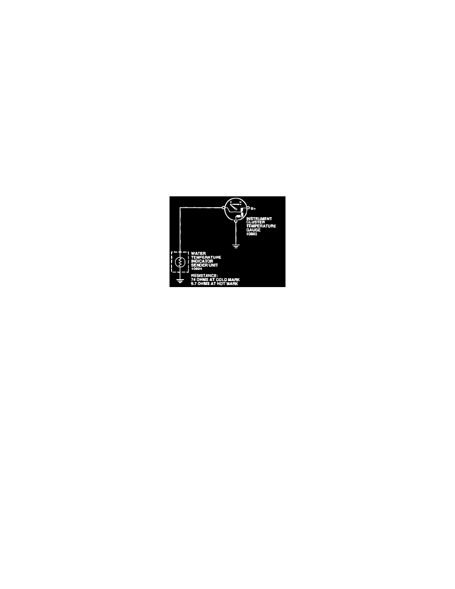
Coolant Temperature Indication System
The coolant temperature indicating system is a magnetic-type indicating system, which consists of the water temperature indicator sender unit (10884)
located in the cylinder block (6010) or cylinder head (6049) and a instrument cluster temperature gauge (10883) in the instrument cluster. The water
temperature indicator sender unit changes resistance according to the temperature of the engine coolant, which vanes the current flow through the
instrument cluster temperature gauge. The pointer position varies proportionally to the current flow. The instrument cluster temperature gauge
resistance is high when the coolant temperature is low, and low when the coolant temperature is high.
The pointer of the magnetic instrument cluster temperature gauge remains in position when ignition switch (11572) is turned to the OFF position. It
will move to the correct indication whenever the ignition switch is turned back to ON position.
The gauge pointer may indicate at the top of the normal band with the coolant temperature within specification, under certain driving conditions such
as heavy traffic or stop and go driving in hot weather.
Instrument Cluster Temperature Gauge
The magnetic instrument cluster temperature gauge movement consists of three primary coils, one of which is wound at a 90 degree angle to the other
two. The coils form a magnetic field which varies in direction according to the variable resistance of the sender unit. A primary magnet, to which a
shaft and pointer are attached, rotates to align to this primary field, resulting in pointer position. The bobbin/coil assembly is pressed into a
metal~housing which has two holes for dial mounting. There is no adjustment, calibration or maintenance required for this instrument cluster
temperature gauge.
CAUTION: Do not remove magnetic gauge pointers; the instrument cluster temperature gauge cannot be recalibrated.
NOTE: An instrument voltage regulator (IVR) is not required for this system.
Water Temperature Indicator Sender Unit
Variations in current flow to the engine coolant temperature gauge occur at the water temperature indicator sender unit. When coolant temperature is
low, the resistance value of the water temperature indicator sender unit is high and very little current flows through the circuit. As the coolant
temperature increases, the resistance level drops, allowing more current flow.