
Escort L4-116 1.9L SOHC (1991)
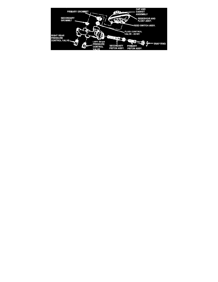
Fig. 17 Pressure Control Valves Installed In Master Cylinder. Front Wheel Drive Models
Proportioner Or Pressure Control Valves
During rapid deceleration, a portion of vehicle weight is transferred to the front wheels. This resultant loss of weight at rear wheels must be compensated
for to avoid early rear wheel skid. The proportioner or pressure control valve reduces rear brake system pressure, delaying rear wheel skid. When the
proportioner or pressure control valve is incorporated in the combination valve assembly, pressure developed within the valve acts against the large end
of the piston, overcoming the spring pressure, moving the piston left, Fig. 15. The piston then contacts the stem seat and restricts line pressure through
the valve.
During normal braking operation, the proportioner or pressure control valve is not functional. Brake fluid flows into the proportioner or pressure control
valve between the piston center hole and the valve stem, through the stop plate and to the rear brakes. Spring pressure loads the piston during normal
braking, causing it to rest against the stop plate, Fig. 16.
On diagonally split brake systems, two proportioners or pressure control valves are used. One controls the left rear brake, the other the right rear brake.
On front wheel drive models less power brakes, the proportioners or pressure control valves are located in the combination valve, Fig. 9. On front wheel
drive models with power brakes, the proportioners or pressure control valves are installed in the master cylinder rear brake outlet ports, Fig. 17.