
Escort L4-116 1.9L SOHC HO (1989)
8. Remove the inertia switch and shield from the existing location and unplug the electrical connector.
9. Fasten the inertia switch and shield to the new bracket, using the old mounting screws.
10. Unwrap about three (3) inches of wire wrap from the wiring harness.
11. Pull the wiring loom to the new location and reconnect the inertia switch wires leaving a small loop (slack) at the bottom. Retape the wiring harness.
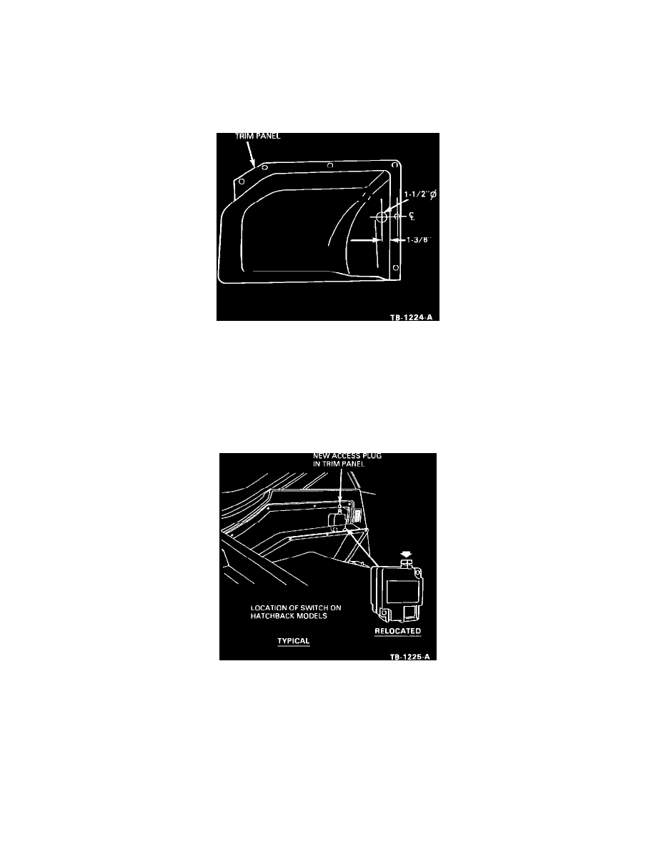
Figure 2
12. Drill a 1-1/2 inch hole in the trim panel for the access plug (N802981-S), Figure 2.
13. Check the reset button on the switch to make sure it is in the down position.
14. After installing the trim panel, check to see if the reset button can be reached through the access hole.
15. Install the access plug from the kit, in the new location.
Figure 3
16. Mark up the illustration in the Owners Manual with a red pen to show that the inertia switch has been relocated. Figure 3 is a typical example.
PART NUMBER
PART NAME
CLASS
E7FZ-9B364-A
Kit - Inertia Switch Bracket
CG
SUPERSEDES:
89-17-10
WARRANTY STATUS:
Eligible Under Basic Warranty Coverage
OPERATION
DESCRIPTION
TIME
900304A
Relocate Inertia Switch
1.0 Hr.