
Escort L4-116 1.9L SOHC HO (1989)
DESCRIPTION AND OPERATION (Continued)
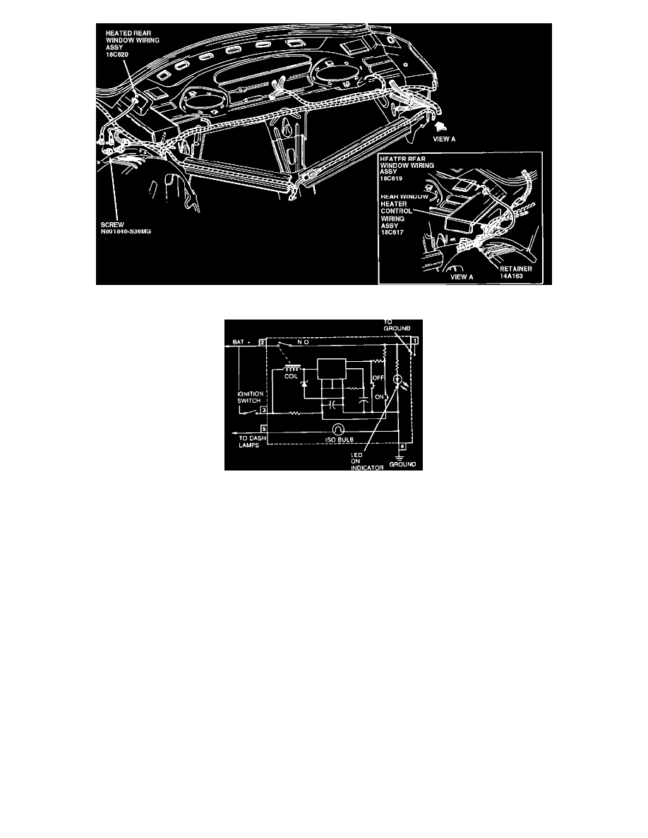
TESTING
Control Assembly Tests
1.
Ground pin 4 and connect a jumper wire between pins 2 and 3. Connect a 12-volt test lamp between pin 1 and ground.
2.
Apply power to pin 2. The test lamp should not light.
3.
Apply power to pin 5. The heated rear window symbol on the switch should light up.
4.
Momentarily actuate the rocker switch to the ON position. The test lamp should come on and stay on after rocker switch returns to the normal
position.
5.
Test lamp should go off under any one or more of the following conditions:
a.
If rocker switch is moved to the OFF position.
b.
Jumper wire between pins 2 and 3.
c.
Approximately 10 minutes have elapsed.
1989 Thunderbird/Cougar
36-86-3
Window, Rear-Defroster
36-86-3
TESTING (Continued)
Grid Wire Test
1.
Using a strong lamp inside the vehicle, visually inspect the wire grid from the outside. A broken grid wire will appear as a brown spot.
2.
Run the engine at idle. Set the control switch to ON. The indicator lamp should come on.
3.
Working inside the vehicle with a 12-volt DC voltmeter such as Rotunda Digital Volt Ohm Meter 007-00001 or equivalent, contact the broad
red-brown strips on the rear window; positive lead to battery side and negative lead to ground side. The meter should read 10-13 volts. A lower
voltage reading indicates a loose ground wire (pigtail) connection at the ground attaching screw.