
Escort L4-121 2.0L SOHC VIN P SFI (2002)
Fan Clutch: Description and Operation
PCM Output
Fan Control
Fan Control
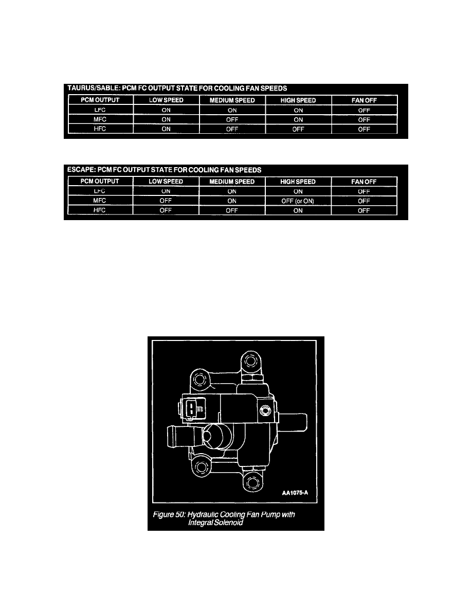
TAURUS/SABLE: PCM FC Output State For Cooling Fan Speeds Chart
ESCAPE: PCM FC Output State For Cooling Fan Speeds Chart
The PCM monitors certain parameters (such as engine coolant temperature, vehicle speed, A/C on/off status, A/C pressure, etc) to determine engine
cooling fan needs. The PCM controls the fan operation through the Fan Control (FC) (single speed fan applications), Low Fan Control (LFC),
Medium Fan Control (MFC) and/or High Fan Control (HFC) outputs.
Although the PCM output circuits for three speed tans are called low, medium and high fan control (FC), cooling fan speed is controlled by a
combination of these outputs. Refer to the table.
Hydraulic Cooling Fan Drive
Hydraulic Cooling Fan Drive
Hydraulic Cooling Fan Pump With Integral Solenoid
The system consists of an engine-driven pump with an integral solenoid (Figure 49) on the pump that is triggered by the powertrain control module
(PCM). Fan speed is controlled by adjusting current to the solenoid, which then changes the fluid flow to the hydraulic motor. More current means the
solenoid opens up, allowing higher pressure to increase the fan speed. The fan always turns due to solenoid current leakage, even in cold engine cases.
The motor is driven by the pump. It contains a shaft on which the fan mounts. The motor also contains quick connect fittings for the high pressure