
Escort L4-122 2.0L SOHC (1997)
0.800 mm (0.031 inch)
0.825 mm (0.032 inch)
0.850 mm (0.033 inch)
0.875 mm (0,034 inch)
0.900 mm (0.035 inch)
0.925 mm (0.036 inch)
0.950 mm (0.037 inch)
0.975 mm (0.038 inch)
1.000 mm (0.039 inch)
1.025 mm (0.040 inch)
1.050 mm (0.041 inch)
1.075 mm (0.042 inch)
1.100 mm (0.043 inch)
1.125 mm (0.044 inch)
1.150 mm (0.045 inch)
1.175 mm (0.046 inch)
1.200 mm (0.047 inch)
1.225 mm (0.048 inch)
1.250 mm (0.049 inch)
1.275 mm (0.050 inch)
1.300 mm (0.051 inch)
1.325 mm (0.052 inch)
1.350 mm (0.053 inch)
1.375 mm (0.054 inch)
1.400 mm (0.055 inch)
1.425 mm (0.056 inch)
1.450 mm (0.057 inch)
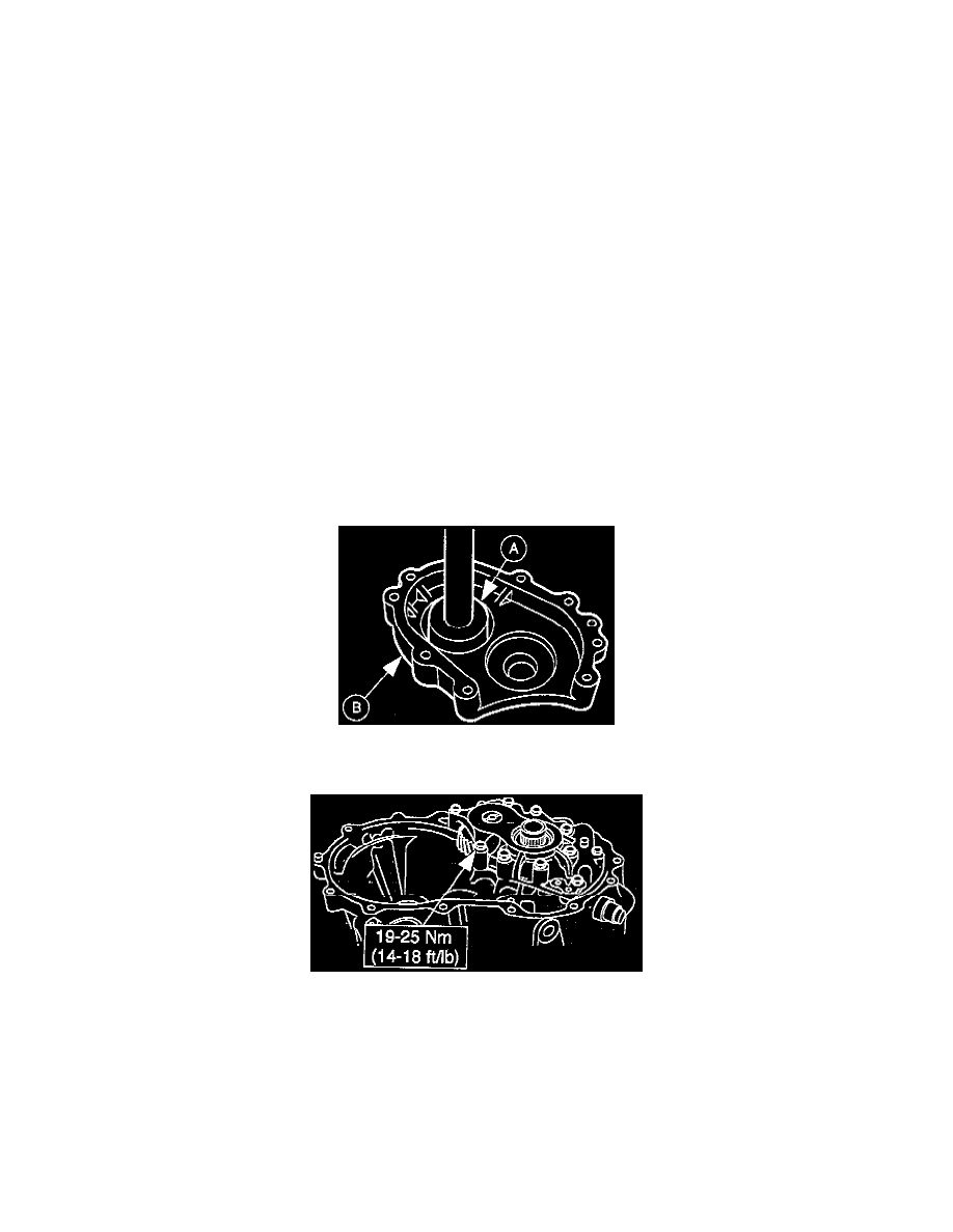
14. Remove the bolts, washers, bearing housing, gauge, and bearing cup. Use (A) Bearing Cup Replacer T77F-1217-B to press the selected shim(s)
and bearing cup into the (B) bearing housing.
15. Install the bearing housing and measure the bearing preload. If the preload measurement is not within specification, repeat the gauging process.
When the proper preload specification has been obtained, remove the bearing housing.