
Escort L4-98 1.6L SOHC VIN 5 FI (1985)
Brake Drum: Service and Repair
Type 4 Drum
Removal
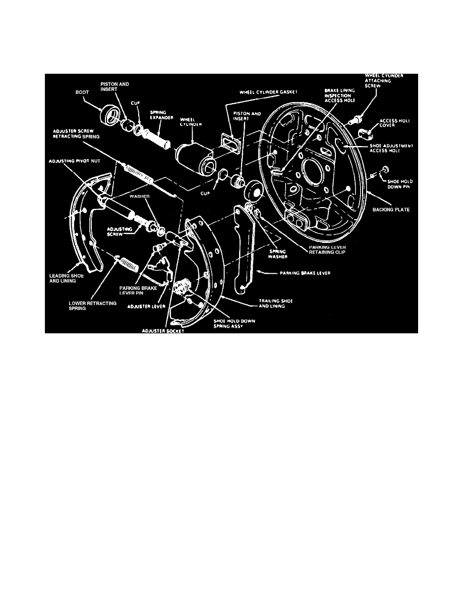
Drum Brake Assembly
1.
Raise and support rear of vehicle, then remove tire and wheel assembly.
2.
Remove brake drum. If brake lining is dragging on brake drum, back off brake adjustment. Refer to individual car chapters for procedure.
3.
Using suitable tool, remove hold-down retainers, springs and pins, Fig. 1.
4.
Remove brake shoes and adjuster assemblies from backing plate by lifting up and away from wheel cylinder assembly. When removing brake
shoe and adjuster assemblies, use care not to bend adjusting lever.
5.
Remove parking brake cable from parking brake lever.
6.
Remove lower retracting spring, adjuster screw retracting spring and adjuster lever.
7.
Separate brake shoes, then remove parking brake lever retaining clip and spring washer and slide lever off parking brake lever pin on the trailing
shoe.
8.
Clean dirt from brake drum, backing plate and all other components. Do not use compressed air or dry brush to clean brake parts. Many
brake parts contain asbestos fibers which, if inhaled, can cause serious injury. Clean brake parts with a water soaked rag or a suitable
vacuum cleaner to minimize airborne dust.
Installation
1.
Lightly lubricate backing plate shoe contact surfaces with suitable brake lubrication.
2.
Remove brake drum hub grease seal and bearings, then clean and repack bearings and reinstall. Install new grease seal.
3.
Assemble parking brake lever to trailing shoe, then install spring washer and retaining clip. Using suitable pliers, crimp retaining clip until securely
fastened.
4.
Attach parking brake cable to parking brake lever.
5.
Assemble lower retracting spring to leading and trailing shoe assemblies, then spread lower part of shoes and install on backing plate.
6.
Using suitable tool, install hold-down springs.
7.
Tighten adjuster assembly, then back off {1-2} turn. Install adjuster assembly between leading shoe slot and trailing shoe/parking brake lever slot.
The adjuster socket end slot must fit into trailing shoe/parking brake lever. Adjuster assemblies are stamped R (right) and L (left). To ensure
proper adjuster operation, they must be installed on their respective sides. The letter must be installed in the upright position, facing