
Escort L4-98 1.6L SOHC VIN 5 FI (1985)
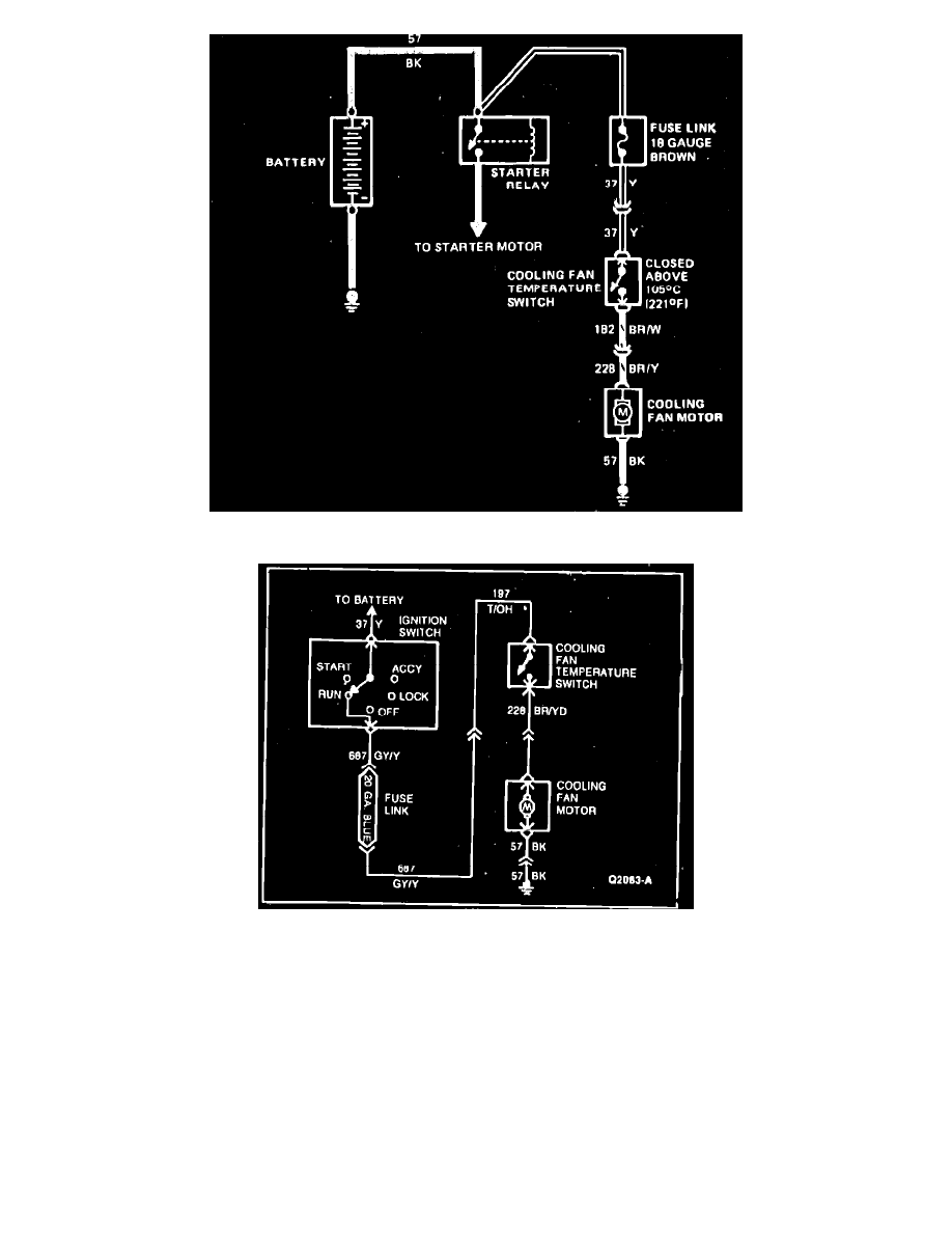
Fig. 32 Electric engine cooling fan wiring diagram. Type 26
Fig. 33 Electric engine cooling fan wiring diagram. Type 27
Refer to Figs. 32 and 33, during the following procedures.
1.
Disconnect fan motor electrical connector, then connect a jumper wire from motor ground connection to a known good ground and a jumper wire
from battery positive terminal to motor B+ connection. If fan motor runs, proceed to step 2. If fan motor does not run, replace motor.
2.
Disconnect cooling fan temperature switch connector, then check for battery voltage on 37 (Y) circuit for Type 26 or 197 (T/OH) circuit for Type
27. If battery voltage exists, proceed to step 3. If battery voltage does not exist, check for opens or shorts in 37 or 197 circuits.
3.
Jump cooling fan temperature switch connector pins together. If fan motor runs, replace temperature switch. If fan motor does not run, proceed to
step 4.
4.
Disconnect fan motor connector, then check for voltage at 228 (BR/Y) terminal with cooling fan temperature switch jumped. If battery voltage is
indicated, proceed to step 5. If battery voltage is not indicated, check 228 and 182 circuits for opens and repair as necessary. Recheck cooling fan
operation.
5.
Check ground circuit (57) for continuity. If continuity exists, replace cooling fan motor and recheck cooling fan operation. If continuity does not
exist, service open in ground circuit (57) and recheck cooling fan operation.