
Escort L4-98 1.6L SOHC VIN 5 FI (1985)
Vacuum Spark Delay Valve: Testing and Inspection
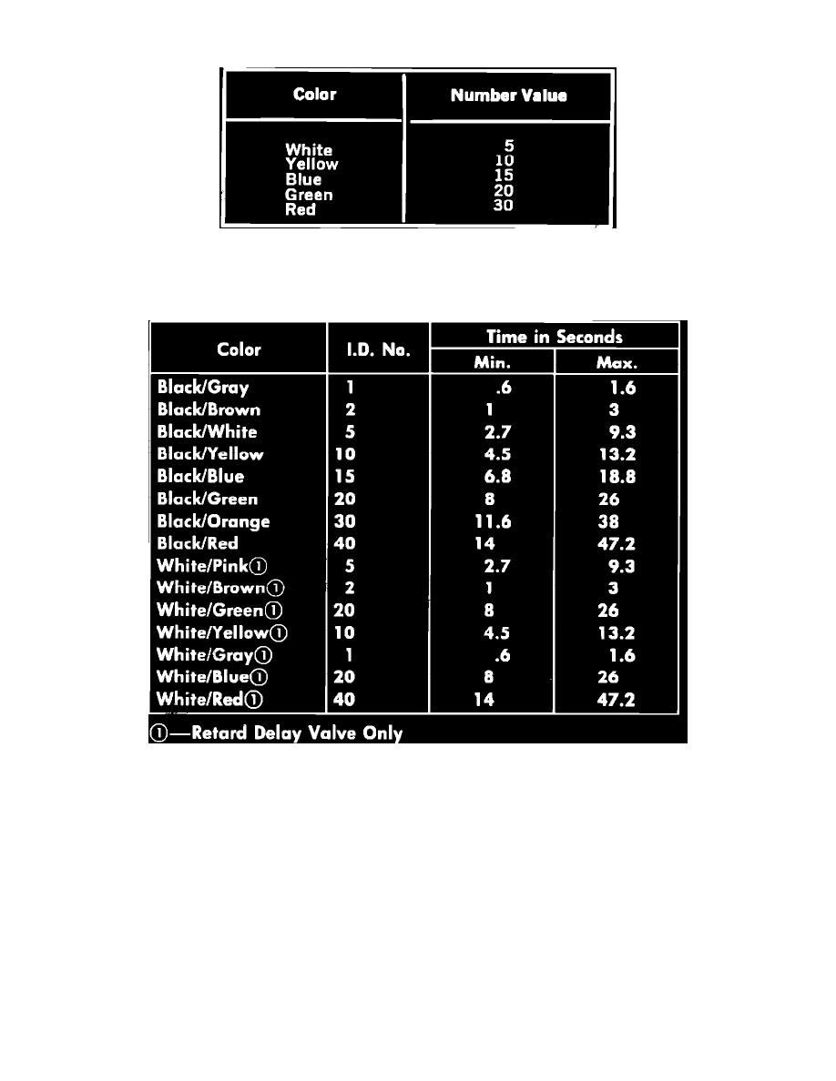
SDV & VDV valve color coding
Refer to Fig. 35, for number value by color code. To perform the following procedure, an external vacuum source capable of maintaining a minimum
constant 10 inches Hg is required.
Vacuum & spark delay valve specifications chart
Mono Delay Valve
1.
Set external vacuum source to 10 inches Hg and connect black side of delay valve to vacuum source.
2.
Connect a vacuum gauge with a 24 inch hose to colored side of delay valve.
3.
Apply 10 inches Hg vacuum and observe time in seconds for gauge to read 0---8 inches Hg. The minimum and maximum time for gauge to read 8
inches Hg should be as shown in Fig. 36.
Dual Delay Valve
1.
Set external vacuum source to 10 inches Hg and connect vacuum gauge with a 24 inch hose to DIST nipple of delay valve.
2.
Connect black side of delay valve and CARB nipple of delay valve to vacuum source. Avoid applying vacuum to CARB nipple while applying
vacuum to black side of valve.
3.
Apply 10 inches Hg of vacuum and observe time in seconds for gauge to read from 0---8 inches Hg. The minimum and maximum time for gauge
to read 8 inches Hg should be as shown in Fig. 36.
Retard Delay Valve
1.
Set external vacuum source to 10 inches Hg and connect colored side of delay valve to vacuum source.
2.
Connect a vacuum gauge with a 24 inch hose to white side of delay valve.