
Escort L4-98 1.6L SOHC VIN 5 FI (1985)
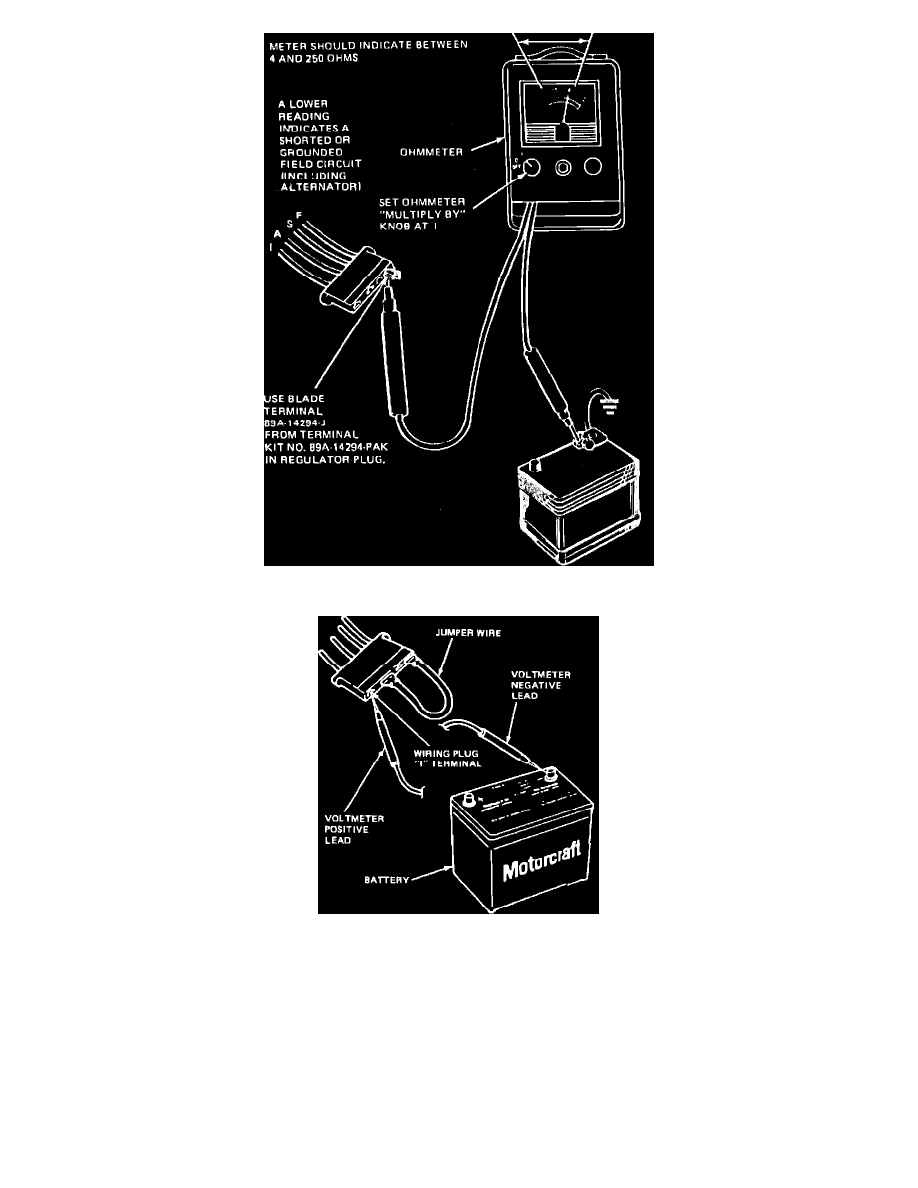
Fig. 11 Regulator plug voltage test
Fig. 12 Testing regulator S and/or I circuit. External Voltage Regulator (EVR)
S AND I CIRCUIT TEST--WITH INDICATOR LIGHT
Exc. Alternators W/Integral Regulator
1.
Disconnect regulator wiring plug, then install a suitable jumper wire between connector ``A'' and ``F'' terminals, Fig. 12.
2.
With the engine idling and negative voltmeter lead connected to battery ground, connect positive lead of voltmeter to S terminal and then to I
terminal of regulator wiring plug, Fig. 11. Voltage of S circuit should read approximately {1-2} of the I circuit. If voltage readings are as
specified, remove jumper wire, replace regulator and connect wiring plug.
3.
If no voltage is present, the wiring is at fault. Service the faulty circuit.