
Escort L4-98 1.6L SOHC VIN 5 FI (1985)
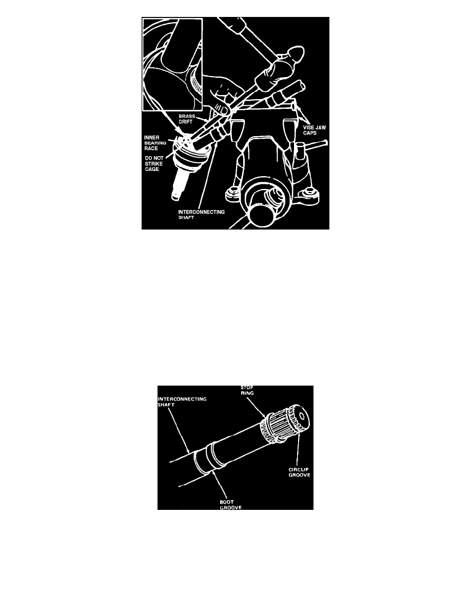
Fig. 6 Separating Constant Velocity Joint From Shaft
LATE 1983 & 1984---87 MODELS
REMOVAL
Except Inboard Constant Velocity Joint & Boot, 5 Speed Manual Transaxle
1.
Place halfshaft in suitable vise. Use caution not to damage boot or clamp.
2.
Cut large boot clamp and remove from boot, Figs. 12 through 14, then position boot upward on shaft. If boot only is being replaced due to
damage, check joint grease for contamination. If joints were operating satisfactorily and grease is not contaminated, add grease and install new
boot. If grease is contaminated, joint must be completely disassembled.
3.
Place interconnecting shaft in a suitable vise and angle constant velocity joint so that inner bearing race is exposed, Fig. 15.
4.
Using suitable drift and hammer, tap inner bearing race to dislodge internal circlip and separate constant velocity joint from interconnecting shaft,
being careful not to drop joint.
5.
Remove boot from shaft, cutting remaining clamp as necessary.
Fig. 8 Stub shaft stop ring
6.
Remove circlip from end of shaft and discard. Inspect stop ring for damage and replace as necessary, Fig. 8.
Inboard Constant Velocity Joint & Boot, 5 Speed Manual Transaxle
1.
Remove large boot clamp, roll boot back, and wipe away excess grease.
2.
Remove wire ring bearing retainer from outer race, then remove outer race.