
Escort L4-98 1.6L SOHC VIN 5 FI (1985)
Wiper Motor: Testing and Inspection
Circuit Breaker Test
On models with a dash mounted rotary wiper switch, the circuit breaker is integral with the switch. On rotary pin type switches normally used with
depressed park wipers, the circuit breaker has a rated capacity of 8{1-4} amps. On rotary blade type switches normally used with non-depressed park
wipers, the circuit breaker has a rated capacity of 7 amps. The circuit breaker used on models with dash mounted slide-type switches and models with
steering column mounted switches is located in the fuse block, and the rated capacity is stamped on the circuit breaker.
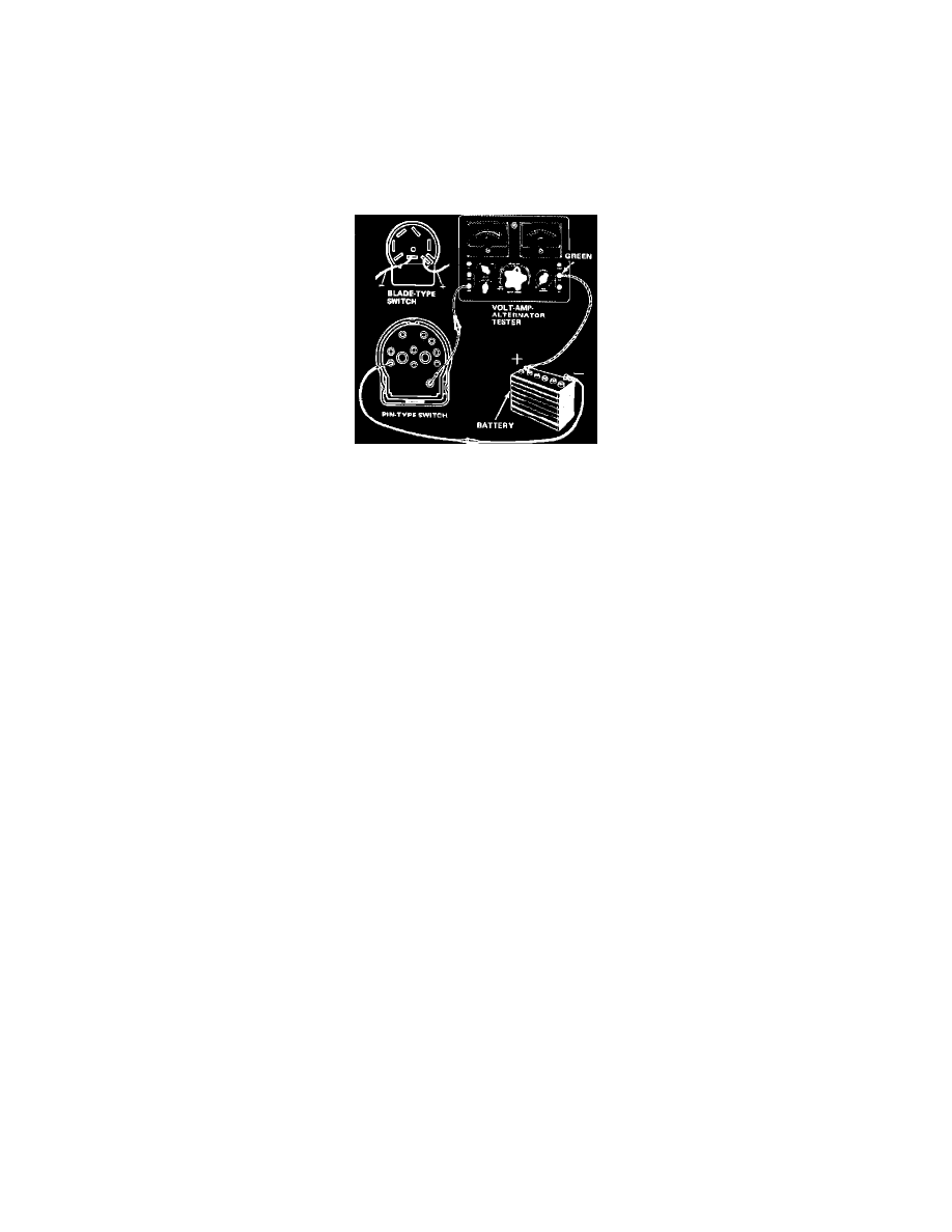
Fig. 16 Windshield wiper switch circuit breaker test connections
TEST 1
1.
Adjust current draw on volt-amp tester until it equals circuit breaker rating.
2.
Connect switch or circuit breaker to tester, Fig. 16, and leave connected for 10 minutes while maintaining current reading on tester at rated
current. If the circuit breaker opens during the 10 minutes, replace the circuit breaker or wiper switch assembly.
TEST 2
1.
Adjust the current draw on the volt-amp tester until it is twice the current rating of the circuit breaker.
2.
Connect switch or circuit breaker as shown in Fig. 16, while maintaining the current draw at twice the rating of the circuit breaker. The current
reading on the ammeter should drop to zero within 30 seconds. If it takes more than 30 seconds for the reading to drop to zero, replace the circuit
breaker or switch assembly.
Motor Testing
Exc. Taurus & Sable
1.
Perform steps 1 through 3 as outlined in ``System Testing.''
2.
Using suitable jumper wires, connect battery voltage to white wire terminal on motor side of electrical connector.
3.
If motor does not run, connect a jumper wire between motor housing and ground.
4.
If motor runs, repair motor ground. If motor does not run, repair or replace motor.
5.
If motor runs in step 2, stop motor with wiper arm at top of travel by disconnecting jumper wire.
6.
Connect battery voltage to red wire terminal on motor side of electrical connector.
7.
If motor does not run to park position and stop, repair or replace motor.
Notes On Testing
If a malfunction exists on models with intermittent wipers and all other components are satisfactory, check intermittent governor ground and/or replace
governor.
System Testing
WIPER MOTOR INOPERATIVE, OR OPERATES AT ONE SPEED ONLY
Non-Depressed Park Type
1.
Check linkage for binding or obstruction and repair as needed.
2.
Place ignition switch in on position.
3.
Slightly separate electrical connector to wiper motor to gain access to terminals, but leave harness connected to motor.
4.
Connect test lamp between red wire terminal at motor and ground. If lamp does not light, check wiper system feed circuit from ignition switch.
5.
Place wiper switch in low position and connect test lamp between white wire terminal at motor and ground.
6.
Place wiper switch in high position and connect test lamp between blue wire terminal at motor and ground.
7.
If lamp does not light in step 5 or 6, check continuity of wiper switch and wiper system wiring. Repair wiring or replace switch as needed.
8.
If lamp lights in steps 5 and 6, check motor as outlined in ``Wiper Motor Current Draw Test.''