
Escort ZX2 L4-2.0L DOHC VIN 3 (2000)
Oxygen Sensor: Description and Operation
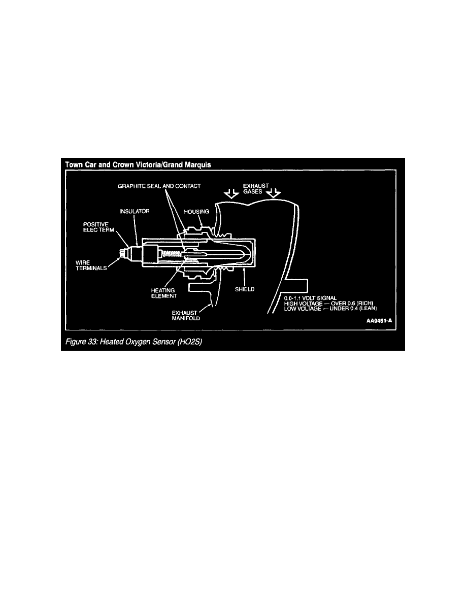
Heated Oxygen Sensor
The upstream Heated Oxygen Sensor (HO2S) is mounted in the exhaust manifold and senses the oxygen concentration in the exhaust gas. It sends this
information to the PCM, which uses the informati6n to determine fuel injection amounts. The sensing element is made of zirconia ceramic with a
platinum coating.
The downstream HO2S is mounted on the muffler inlet pipe just below the Three Way Catalytic Converter (TWC). The downstream HO2S monitors the
TWC and transmits the information to the PCM.
The Heated Oxygen Sensor (HO2S) detects the presence of oxygen in the exhaust and produces a variable voltage according to the amount of oxygen
detected. A high concentration of oxygen (lean air/fuel ratio) in the exhaust produces a low voltage signal less than 0.4 volt. A low concentration of
oxygen (rich air/fuel ratio) produces a high voltage signal greater than 0.6 volt. The HO2S provides feedback to the PCM indicating air/fuel ratio in
order to achieve a near stoichiometric air/fuel ratio of 14.7:1 during closed loop engine operation. The HO2S generates a voltage between 0.0 and 1.1
volts.
Heated Oxygen Sensor (HO2S)
Embedded with the sensing element is the HO2S heater. The heating element heats the sensor to temperatures of 800°C (1400°F). At approximately 300
°C (600°F) the engine can enter closed loop operation. The VPWR circuit supplies voltage to the heater and the PCM will complete the ground when the
proper conditions occur. For model year 1998 a new HO2S heater and heater control system are installed on some vehicles. The high power heater
reaches closed loop fuel control temperatures. The use of this heater requires that the HO2S heater control be duty cycled, to prevent damage to the
heater. The 6 ohm design is not interchangeable with new style 3.3 ohm heater.