
Escort ZX2 L4-2.0L DOHC VIN 3 (2000)
Alternator: Testing and Inspection
Generator Testing
Base Voltage Test
NOTE: Prior to running this test, turn the head lamps on for 10-15 seconds to remove any surface charge from the battery. Then, wait until the voltage
stabilizes before performing the Generator Base Voltage Test. The battery should be at the recommended state of charge.
1. With the ignition OFF and no electrical loads on, connect the ARBST Voltmeter Negative Lead to the battery ground cable clamp.
2. Connect the positive lead of the ARBST to the battery to starter relay cable clamp.
3. Press the MULTIMETER button.
4. Read and record the battery voltage shown on the display. This is called base voltage and will be used in later tests.
Field Circuit Drain Test
Connect the voltmeter negative lead to the generator rear housing for all of the following voltage readings:
1. With the ignition switch turned to the LOCK position, connect the voltmeter positive lead to the voltage regulator F-terminal. The meter should
indicate battery voltage if the system is operating normally. If less than battery voltage is indicated, proceed to Step 2 to find the cause of the
current drain.
2. Measure the voltage at the I-terminal with the ignition switch in the LOCK position. If voltage is indicated, REPAIR the I-circuit from the ignition
switch to eliminate the voltage source.
Generator On - Vehicle Tests
NOTE: Battery posts and cable clamps must be clean and tight to ensure accurate meter indications.
When performing charging system tests, turn off all lamps and electrical components. Place transmission in NEUTRAL and apply parking brake.
Charging System Testing - ARBST Method
1. Connect the positive and negative leads of the ARBST to the battery terminals.
2. Remove the gray amp probe from any conductor and press ZERO AMPS.
3. Connect the gray amp probe around the battery ground cable(s) so that the arrow on the probe points toward the battery.
NOTE: The gray amp probe MUST be secured around all wires connected to the vehicle negative battery terminal.
4. Start the vehicle engine.
5. Press CHARGING SYSTEM TEST.
NOTE: The display must indicate the correct number of cylinders for the RPM reading to be accurate. The ARBST will automatically default to
4 cyl. To change the number of cylinders, press the appropriate number on the numeric keypad.
6. Follow the screen prompt and adjust the RPM as directed. The ARBST will load and unload the charging system under various conditions.
7. Read the results, press CONTINUE to toggle between REGULATOR VOLTS, PEAK AMPS and DIODE CONDITION.
NOTE: If the amperage remains higher than 20 amps during the test, an asterisk (*) appears near regulated volts on the display. Regulated volts
are probably lower than normal because charging current was very high.
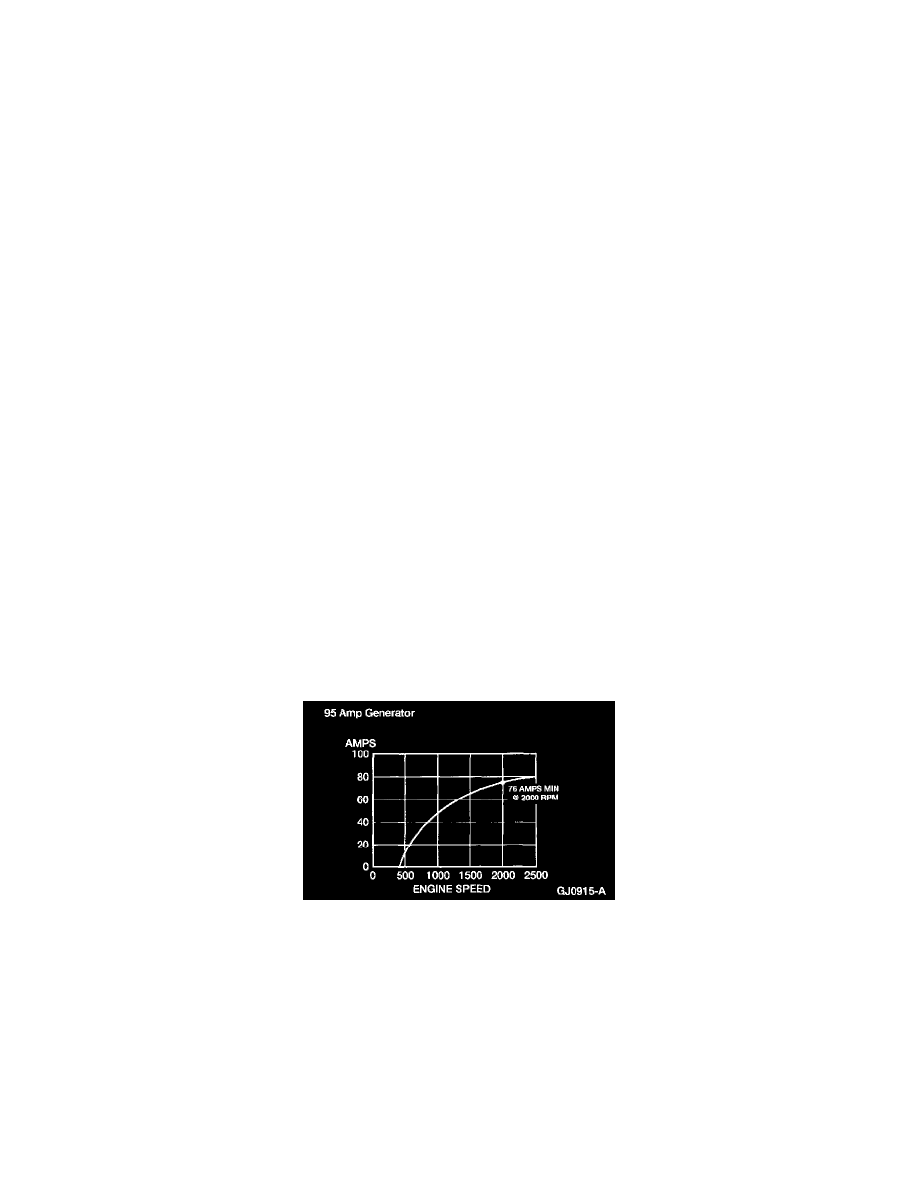
8. Generator output should be greater than shown on the graph. If routed here from a pinpoint test, return to the pinpoint test See: Testing and
Inspection/Pinpoint Tests. If not, refer to Symptom Chart for diagnostic procedures. See: Testing and Inspection/Symptom Related Diagnostic
Procedures
Load Test
1. With the engine running, turn on the air conditioner (if equipped), turn the blower motor to high speed and the headlamps to high beam.
2. Increase the engine speed to approximately 2000 rpm. The voltage should increase a minimum of 0.5 volts above the base voltage. If the voltage