
Excursion 4WD V8-6.0L DSL Turbo VIN P (2004)
4.
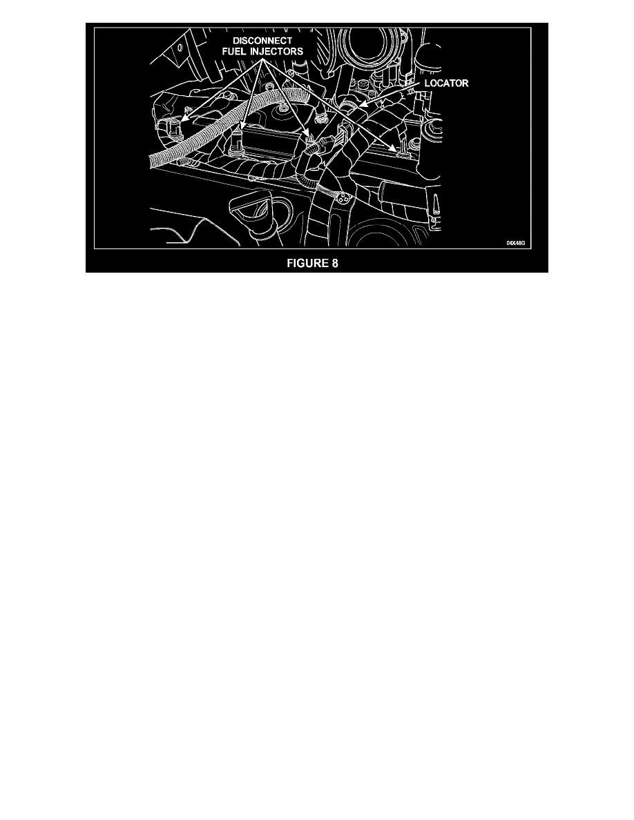
Disconnect the four (4) passenger-side injector connectors and the one (1) retainer located behind the alternator. Remove the harness from the
vehicle by carefully pulling it from under the turbocharger towards the driver side of the vehicle. See Figure 8.
INSTALLATION
1.
Route the new harness under the turbocharger and secure the retainer behind the alternator.
2.
Connect the four (4) injector connectors on the passenger side of the engine.
3.
Position the harness along the driver side of the engine and connect the four (4) injector connectors.
4.
Secure the three (3) wire harness retainers (two (2) located along the fuel injector manifold assembly and one (1) located under the turbocharger).
5.
Connect the ground wire at the intake manifold and reattach the engine harness to the stud. Hold the stud to prevent the ground wire from rotating
and twisting.
6.
Position the FICM and connect all three (3) FICM connectors.
7.
Install the FICM retainer bolts. Tighten the bolts to 13 Nm (10 lb-ft).
8.
Proceed to Sensor Connector Replacement in this Attachment V.
SENSOR CONNECTOR REPLACEMENT
NOTE:
All splices are to be made using tools provided in the Rotunda Wire Splice Tool Kit 164-R5903.
The repair kits contain the connector and pigtail, butt splice connector and heat shrink tubing.