
EXP L4-098 1.6L VIN 2 2-bbl (1983)
Fuel Pressure Release: Service and Repair
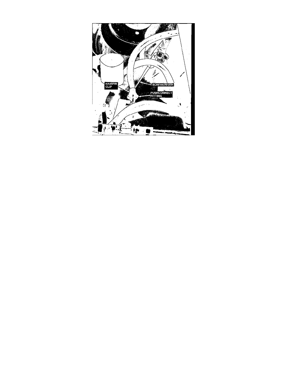
Fig. 12 Disconnecting fuel supply line
NOTE: If any subassemblies of the system are to be serviced and/or replaced with the fuel charging assembly installed on the engine, the following
steps must be taken:
1. Disconnect battery ground cable.
2. On four cylinder engines, drain engine coolant from radiator.
3. On all models, remove gas cap to release residual fuel pressure in the tank.
4. Remove valve cap from fuel pressure relief valve on fuel supply manifold. Using tool No. T80L-9974-A or equivalent, release fuel system
pressure at the valve.
5. On 4-97.6 engines, proceed as follows:
a. Disconnect the push-connect fuel supply line. Insert screwdriver under hairpin clip and disengage clip from fitting, Fig 12.
b. Tag and disconnect fuel return lines and vacuum connections. When disconnecting fuel lines, wrap a clean towel around fittings to avoid
spillage.
c. Disconnect sensor in heater supply tube under lower intake manifold, then the electronic engine control and injector electrical connectors.
d. Disconnect air bypass electrical connector from electronic engine control harness.
6. On 4-116 engines, proceed as follows:
a. Disconnect fuel supply and return lines using tool No. T81P-19623-G or G1 or equivalent.
b. Disconnect injector wiring harness by disconnecting ECT sensor in heater supply tube below lower intake manifold and EEC harness.
c. Disconnect air bypass electrical connector from EEC harness.
7. On V6-182 engines, proceed as follows:
a. Disconnect fuel supply and return lines using tool No. T81P-19623-G or equivalent.
b. Disconnect electrical connectors from injectors.
c. Disconnect electrical connectors from throttle position sensor, air bypass valve and air charge temperature sensor.