
EXP L4-098 1.6L VIN 4 2-bbl (1982)
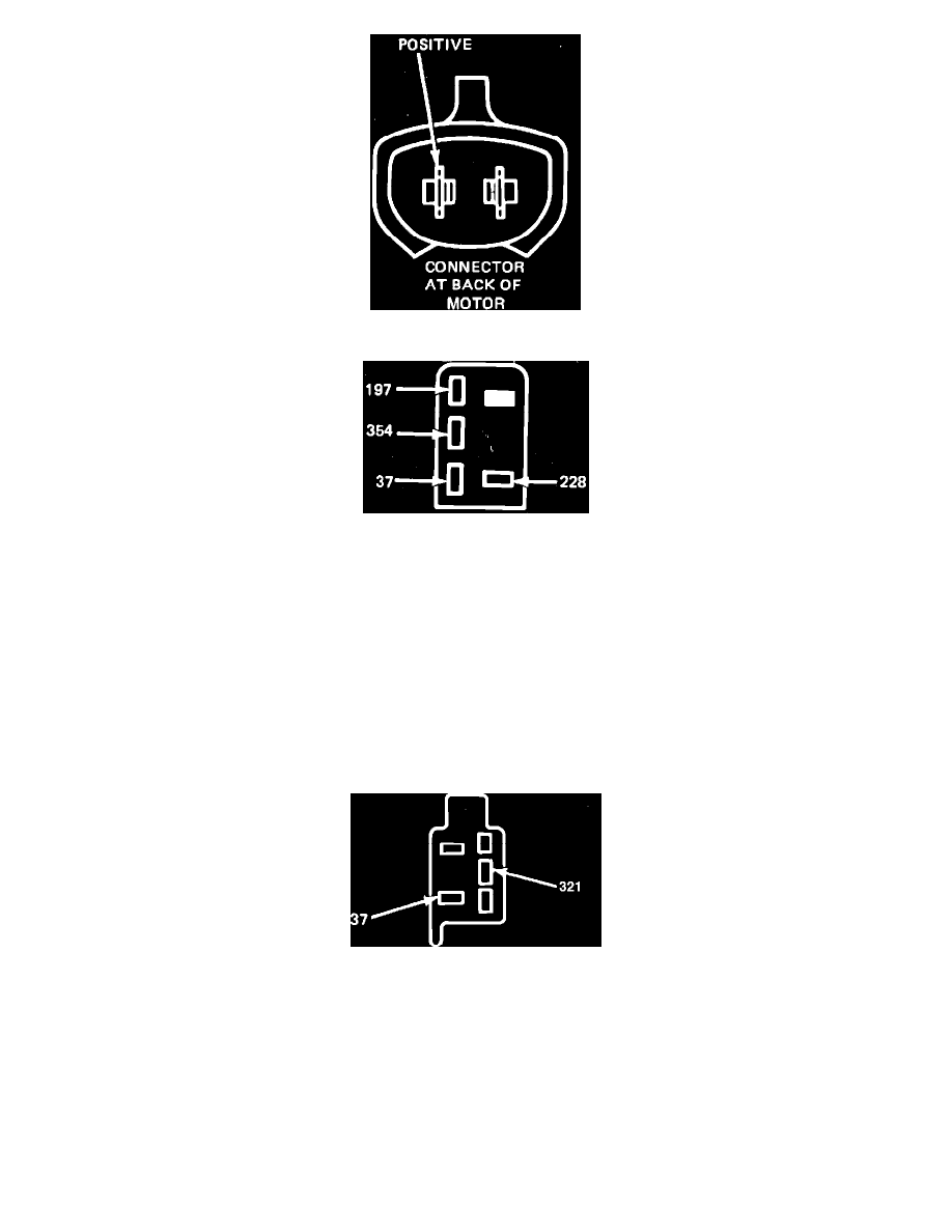
Fig. 5 Fan motor terminal identification
Fig. 9 Cooling fan relay connector terminal identification. Type 4
5.
Disconnect cooling fan motor connector, then connect a jumper wire from motor ground connection to a known good ground and a jumper wire
from battery positive to motor B+ connection, Fig. 5. If fan motor does not run, replace motor. If fan motor runs, proceed to step 6.
6.
Using an ohmmeter, check fan motor ground. If continuity exists, proceed to step 7. If continuity does not exist, repair ground.
7.
Remove jumper wires, then reconnect fan motor connector. Disconnect cooling fan relay connector and switch ignition ``On.'' Using a test light,
check for voltage at terminals 37 and 354, Fig. 9. If there is no voltage at one or both terminals, repair relay feed circuits. If there is voltage at both
terminals, proceed to step 8.
8.
Jump terminals 37 to 228 of cooling fan relay connector, Fig. 9. If fan motor does not run, repair wiring from relay connector to fan motor
connector. (check capacitor, if equipped.) If fan motor runs, proceed to step 9.
9.
Remove jumper wires. Using an ohmmeter, check continuity of wire 354 from relay connector to coolant temperature switch connector, Fig. 9. If
continuity does not exist, repair wires and/or connectors. If continuity does exist, replace cooling fan relay and retest.
10.
Disconnect A/C relay connector. Using an ohmmeter, check continuity of wire 228 from relay to motor. If continuity does not exist, repair wires
and/or connectors. If continuity does exist, proceed to step 11.
Fig. 7 A/C relay wire connector terminal identification
11.
Reconnect fan motor connector, then disconnect A/C relay connector. Set A/C controls on maximum and turn ignition ``On.'' Using a test light,
check for voltage at terminals 37 and 321, Fig. 7. If there is no voltage at terminal 37, repair relay connector feed circuit. If there is no voltage at
terminal 321, proceed to step 13. If there is voltage at both terminals, proceed to step 12.
12.
Reconnect A/C relay connector. Connect jumper wire to base of relay to a known good ground. If fan motor does not run, replace relay and retest
step 4. If fan motor runs, clean relay ground.
13.
Using a test light, test for voltage at circuit 296 of A/C function control harness. If voltage exists, proceed to step 14. If no voltage exists, repair
feed wire from fuse box.
14.
Using an ohmmeter, check continuity of terminals 296 to 321 in A/C function control. Continuity should only exist in the following positions: A/C
Max., A/C Norm. and Defrost. If continuity is not satisfactory, replace A/C function control. If continuity is satisfactory, proceed to step 15.
15.
Using an ohmmeter, check continuity of circuit 321 from A/C function control to A/C relay. If continuity does not exist, repair wiring and/or
connectors. If continuity does exist, repeat step 11.