
Expedition 4WD V8-281 4.6L SOHC (1998)
3. Mark the driveshaft flange and the driveshaft rear axle companion flange for correct alignment during installation.
4. Wipe the lubricant from the internal working parts, and visually inspect the parts for wear or damage.
5. Rotate the differential case to see if there is any roughness which would indicate damaged bearings or gears.
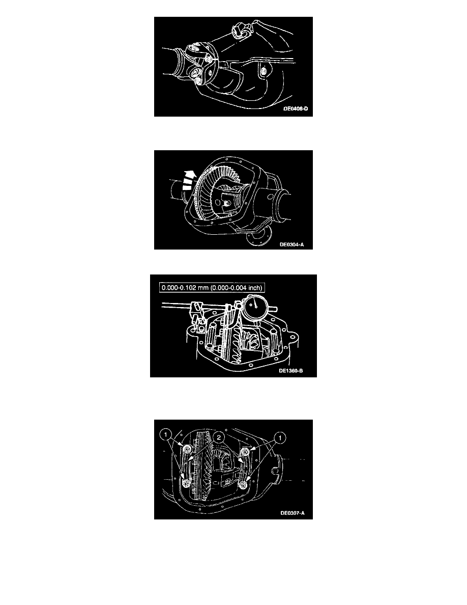
6. NOTE: There is a space between the anti-lock speed sensor ring and the ring gear for measuring ring gear backface runout.
Position the Dial Indicator with Bracketry, and inspect ring gear backlash and ring gear backface runout.
7. CAUTION: The bearing caps must be installed in their identical locations and positions. Mark each bearing cap before removal.
Loosen the differential case.
1
Remove the bearing cap bolts.
2
Remove the bearing caps.