
Expedition 4WD V8-4.6L SOHC VIN W (1999)
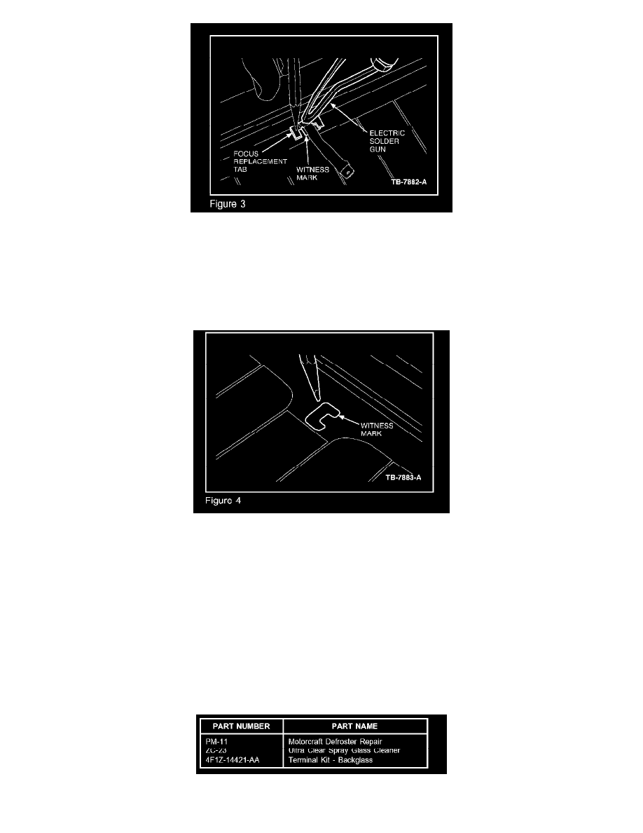
Use terminal type A (Figure 2) for all tab locations except on the Focus vehicle line. For the Focus, use type B (Figure 3).
NOTE
DEPENDING ON THE ORIGINAL TERMINAL LOCATION, AND WHETHER THE TERMINAL IS COVERED BY PILLAR TRIM, WILL
DETERMINE WHERE TO LOCATE THE NEW TERMINAL. SOME GRID LINE BUSS-BARS MAY ONLY ALLOW THE PLACEMENT OF
THE TERMINAL ABOVE OR BELOW THE ORIGINAL TAB LOCATION DUE TO SPACE LIMITATIONS, BUT FOR MOST VEHICLE
APPLICATIONS THE REPLACEMENT TAB LOCATION WILL COVER THE ORIGINAL TAB LOCATION BUT STILL ALLOW THE
REPLACEMENT TAB TO ATTACH TO THE BUSS-BAR ON GOOD CONDUCTIVE MATERIAL.
1.
Place the replacement terminal over the original tab location making sure the conductive areas of the terminal will be on a good conductive area.
Do not place the terminal tab foot on the original location which does not have conductive material (figure 4).
2.
Hold the terminal in place with an item such as regular lead pencil at a 90 degree angle from the terminal. (Terminal type B can be held in place
with tape.) (Holding at other than a 90 degree angle may allow the terminal to slip when the solder liquefies).
3.
Place the soldering gun tip on the top of the terminal but not on the painted areas of the tab. Energize the soldering gun and watch for the painted
area of the terminal to liquefy and change color. The paint should liquefy in approximately 25-45 seconds after heating. As soon as the paint color
completely changes on either side of the terminal, de-energize the soldering gun and continue to hold the terminal in place with the soldering gun
and pencil for an additional thirty (30) seconds.
4.
Remove the soldering gun and pencil from the terminal. The terminal should be allowed to cool for another two (2) minutes before the wiring lead
is attached to the terminal.
5.
Attach the electrical lead connection to this terminal, turn on the rear defroster, and verify operation.
Parts Block