
Expedition 4WD V8-5.4L SOHC VIN 5 (2005)
20. Disconnect the LH and RH knock sensor (KS) electrical connectors.
21. Remove the nut and disconnect the engine wiring harness retainer from the CMCV stud.
22. CAUTION: Do not use metal scrapers, wire brushes, power abrasive discs or other abrasive means to clean the sealing surfaces. These tools
cause scratches and gouges which make leak paths. Use a plastic scraping tool to remove all traces of old sealant.
Remove the intake manifold and discard the gaskets.
^
Clean and inspect the sealing surfaces with metal surface prep. Follow the directions on the packaging.
Installation
1. NOTE: Electrical and vacuum harnesses must not restrict movement of the charge motion control valve (CMCV) control rods at rear of the intake
manifold. Use extreme care on installation of the intake manifold to prevent any pinching of electrical and vacuum harnesses.
Using new intake manifold gaskets, position the intake manifold.
2. Using new gaskets, position the coolant crossover and install the 3 bolts
^
Tighten to 10 Nm (89 inch lbs.).
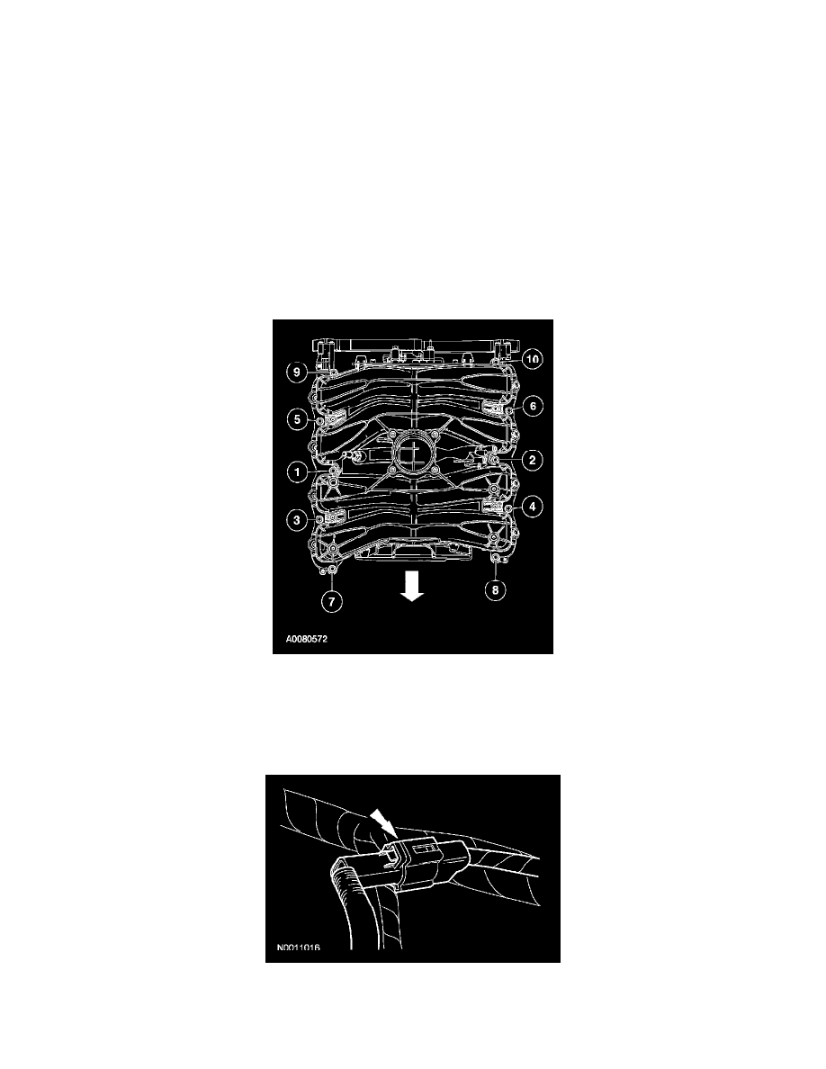
3. Install the intake manifold bolts and tighten in 2 stages in the sequence shown.
^
Stage 1: Tighten to 2 Nm (18 inch lbs.).
^
Stage 2: Tighten to 10 Nm (89 inch lbs.).
4. Connect the engine wiring harness retainer to the CMCV stud and install the nut.
^
Tighten to 10 Nm (89 inch lbs.).
5. Connect the CMCV electrical connector.
6. Connect the cylinder head temperature (CHT) sensor jumper harness electrical connector.