
Expedition 4WD V8-5.4L VIN 5 (2006)
1. Drain the cooling system. For additional information, refer to Cooling System.
2. Disconnect the fuel supply hose spring lock coupling from the fuel rail. For additional information, refer to Fuel Delivery and Air Induction.
3. Remove the generator. For additional information, refer to Alternator.
4. Remove the air cleaner. For additional information, refer to Fuel Delivery and Air Induction.
5. Disconnect the upper radiator hose from the thermostat housing.
6. Disconnect the heater coolant hose from the coolant bypass tube.
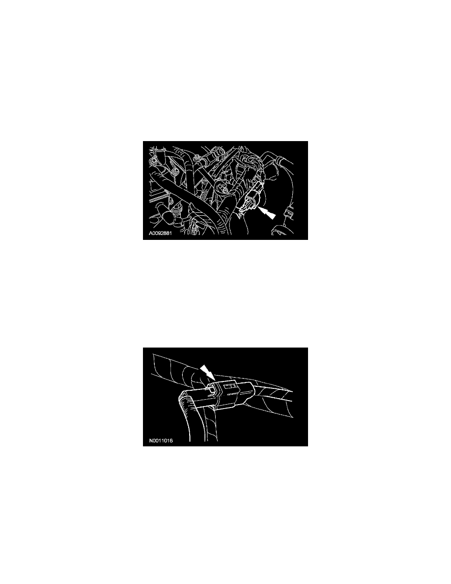
7. Disconnect the quick connect coupling and remove the evaporative emissions system (EVAP) tube from the intake manifold. For additional
information, refer to Fuel Delivery and Air Induction.
8. Disconnect the quick connect couplings and remove the positive crankcase ventilation (PCV) tube. For additional information, refer to Fuel
Delivery and Air Induction.
9. Disconnect the fuel rail pressure and temperature sensor electrical connector and vacuum connector.
10. Disconnect the 8 fuel injector electrical connectors.
11. Disconnect the throttle position (TP) sensor and electronic acceleration control electrical connectors.
12. Disconnect the heated PCV intake fitting electrical connector.
13. Disconnect the brake booster vacuum hose from the intake manifold vacuum tube.
14. Remove the 10 intake manifold bolts
15. CAUTION: Do not use metal scrapers, wire brushes, power abrasive discs or other abrasive means to clean the sealing surfaces. These tools
cause scratches and gouges which make leak paths. Use a plastic scraping tool to remove all traces of old sealant.
Remove the 3 bolts, the coolant bypass tube and discard the gaskets.
^
Clean and inspect the sealing surfaces with silicone gasket remover and metal surface prep. Follow the directions on the packaging.
16. Disconnect the charge motion control valve (CMCV) electrical connector.
17. Disconnect the manifold vacuum tube from the valve cover stud and the support bracket.
18. Disconnect the cylinder head temperature (CHT) sensor jumper harness electrical connector.