
Explorer 2WD V6-245 4.0L (1994)
4.
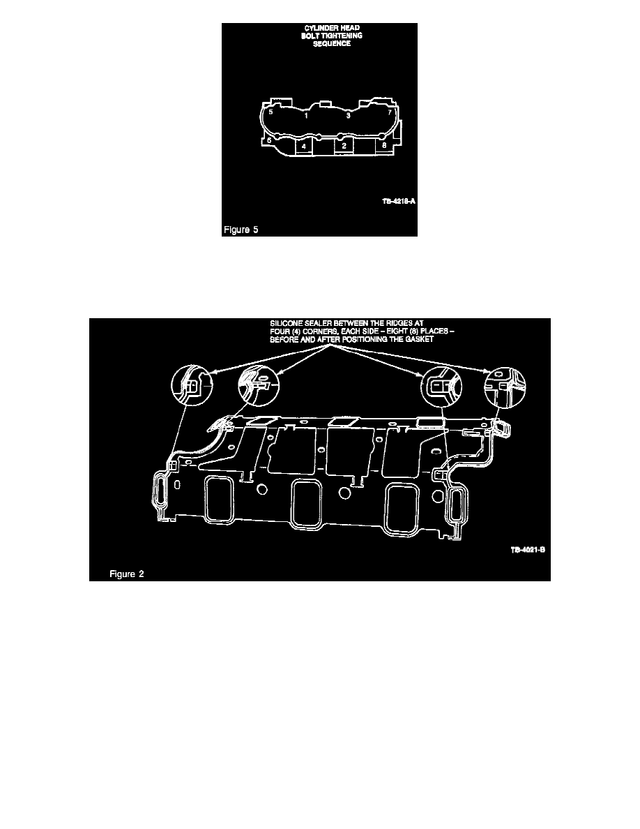
Install and torque cylinder head bolts, in the sequence shown. to 30 N-m (22 lb.ft) (Figure 5).
NOTE:
THE SILICONE SEALER, APPLIED IN THE FOLLOWING STEP, WILL SET-UP IN APPROXIMATELY 15 MINUTES. THE INTAKE
MANIFOLD MUST BE INSTALLED IMMEDIATELY AFTER THE SEALER IS APPLIED.
5.
Apply a small amount (peanut size) of Silicone Rubber Sealer, Loctite 598 (F1AZ-19562-A) on the bottom side of the gasket at the four (4)
corners (Figure 2). The sealer should be applied between the ridges (Figure 2).
6.
Position the gasket with the help of the two (2) temporary guide studs (Item 3 Figure 6) located in Positions 3 and 4 (Figure 7), and slide the
gasket down to its final position in the valley. Then apply a small amount (peanut size) of Silicone Rubber Sealer, Loctite 598 (F1AZ-19562-A) on
the top side of the gasket at the tour (4) corners between the ridges (Figure 2).
NOTE:
IF INTAKE MANIFOLD REPLACEMENT IS REQUIRED AS DETERMINED FROM EARLIER INSPECTION PROCEDURE, AND WHEN
REPLACING WITH A 1995 MANIFOLD, DIFFERENT MANIFOLD BOLTS ARE TO BE USED AS WHEN REPLACING WITH A
PREVIOUS YEAR MANIFOLD. ALSO, AN ADDITIONAL TORQUE STEP IS REQUIRED WITH THE 1992-94 MANIFOLD. THE 1995
MANIFOLD CAN BE IDENTIFIED BY TWO METHODS: (1) THE BLUE DOT BENEATH THE SUFFIX OF PART NUMBER FOTZ-9424-A,
(2) THE SPOTFACE AREAS AS PER FIGURE 8. USE THIS METHOD IF NO BLUE DOT IS VISIBLE.