
Explorer 2WD V6-245 4.0L (1994)
7.
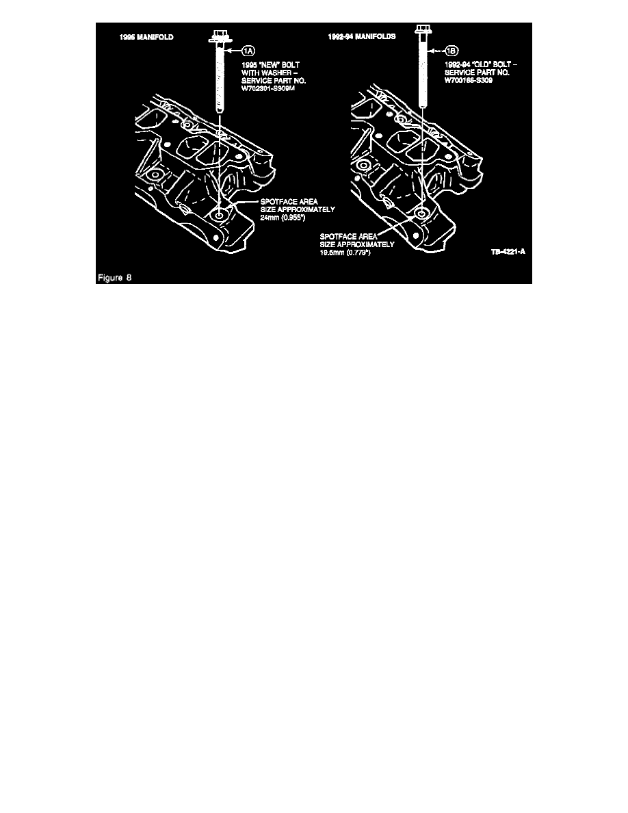
Position the lower intake manifold on the two (2) guide studs and install the nuts and bolts handtight. See Figures 6 and 8 for proper bolt selection,
depending on the manifold year. Torque the intake manifold bolts, in sequence, to 4 N-m (3 lb.ft.) (Figure 7). Replace the two (2) studs with bolts
(save the studs for use when necessary on future jobs).
NOTE:
MODEL YEAR 1995 BOLTS WITH CAPTIVE WASHERS ARE NOT USABLE ON INTAKE MANIFOLDS OF PREVIOUS MODEL YEARS.
8.
Torque the cylinder head bolts, in sequence, to 70 N-m (52 lb.ft.) (Figure 5).
9.
Torque the intake manifold bolts, in sequence, to 8 N-m (6 lb.ft.) (Figure 7).
10.
For the final cylinder head torque step, rotate the cylinder head bolts 90 degrees in sequence (Figure 5).
11.
If using bolts with a captive washer (1995 manifold), finish tightening the intake manifold, in sequence, to 15 N-m (11 lb.ft.). If using bolts
without a captive washer (1990-94 manifold), tighten an additional step to 21 N-m (15 lb.ft.).
12.
Install the valve push rods. Install the rocker arms as outlined in the Service Manual.
13.
Install the valve covers as outlined in "Valve Cover and Gasket Installation Procedure" in this TSB article.
INSTALLATION PROCEDURE AFTER REMOVING ONLY THE INTAKE MANIFOLD
1.
Before installing the new gaskets, remove all old sealer from the intake, heads and block surfaces, and check for proper surface condition. Clean
all exposed areas very thoroughly with Metal Surface Cleaner (F4AZ-19A536-RA) or denatured alcohol.
CAUTION:
DO NOT USE A SAND DISK OR SIMILAR POWER TOOL. IF THE INTAKE MANIFOLD SURFACE IS PITTED (FIGURE 1), THEN THE
MANIFOLD MUST BE REPLACED.
NOTE:
IF THE ENGINE RECEIVED HAS BOLTS INSTEAD OF GUIDE STUDS (ITEM 3, FIGURE 6), THEN TEMPORARILY REPLACE BOLTS
WITH GUIDE STUDS (W701104-S309). IF GUIDE STUDS ARE NOT IN STOCK, FABRICATE BY REMOVING THE HEADS FROM TWO
(2) BOLTS (W700166-S309). INSTALL THEM SNUGLY IN THE CYLINDER BLOCK HOLES THAT MATCH HOLES 3 AND 4 (FIGURE 7).
IF GUIDE STUDS WERE ON THE VEHICLE RECIEVED, THEN LOOSEN THE STUDS 1/2 TURN BEFORE PROCEEDING.
NOTE:
THE SILICONE SEALER, APPLIED IN THE FOLLOWING STEP, WILL SET-UP IN APPROXIMATELY 15 MINUTES. THE INTAKE
MANIFOLD MUST BE INSTALLED IMMEDIATELY AFTER THE SEALER IS APPLIED.
2.
Apply a small amount (peanut size) of Silicone Rubber Sealer, Loctite 598 (F1AZ-19562-A) on the bottom side of the gasket at the four (4)
corners (Figure 2). The sealer should be applied between the ridges (Figure 2).