
Explorer 2WD V6-245 4.0L (1994)
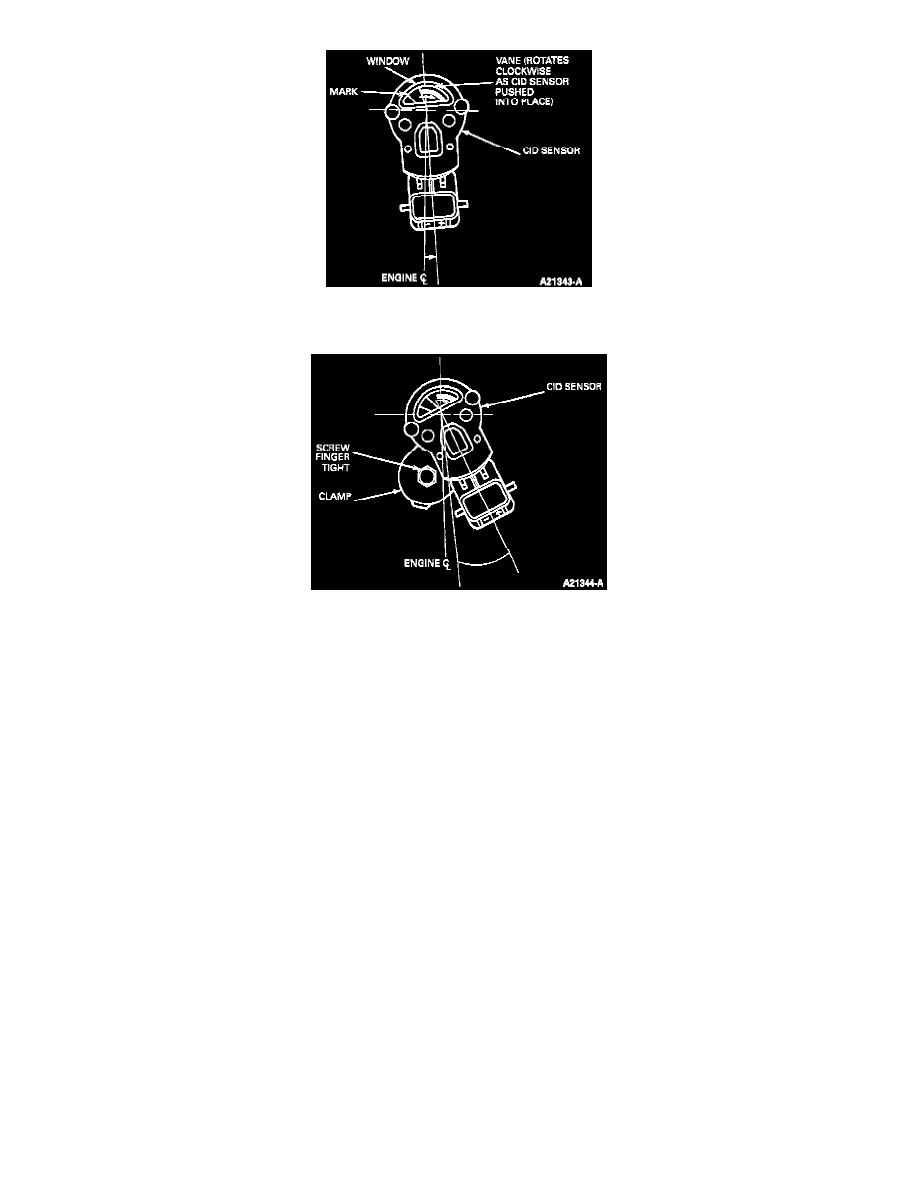
6. Install the assembled CMP sensor and oil pump drive gear into the engine. As the assembly is pushed into place, the camshaft gear will rotate the
sensor vane clockwise toward the center window.
7. Rotate the CMP sensor counterclockwise. Install clamp and screw finger-tight. Rotate the sensor back to its position at right angles to the back of
the block.
8. Connect the CMP Testing Wiring Harness T94T-50-B or equivalent to the CMP sensor.
9. Connect the CMP Testing Wiring Harness leads:
Red harness wire to the battery positive terminal.
Black harness wire to battery negative terminal.
Voltmeter positive lead to harnesses white lead.
Voltmeter negative lead to battery negative terminal.
10. Rotate engine two revolutions to take up slack in timing chain and return to No. 1 cylinder to its compression stroke.
11. Verify that No. 1 cylinder is on its compression stroke.
NOTE: No. 1 cylinder must be at 26 degrees ATDC to set CMP sensor.
12. Continue to rotate the crankshaft until the new 26 degrees ATDC mark lines up with the timing pointer.
13. While rotating the CMP sensor, note the exact point where the sensor switches from 0 to 12 volts on the voltmeter.
NOTE: The voltmeter will register battery voltage whenever the CMP closes and makes a complete circuit.
14. Rotate the CMP sensor clockwise past the CMP switching point (from 12 to 0 volts).
NOTE: The final movement to set the CMP sensor must be in a counterclockwise direction.
15. Rotate the CMP sensor counterclockwise and stop at the exact point the voltmeter switches from 0 to 12 volts.