
Explorer 2WD V6-245 4.0L SOHC VIN E EFI (1997)
Compressor Clutch Relay: Testing and Inspection
RELAY COMPONENT TEST
Testing of an ISO relay can be accomplished through the use of three No. 10 (or larger gauge) jumper wires and a 73 Digital Multimeter or
equivalent. Remove (unplug) the relay to be tested from the engine compartment fuse junction panel, I/P fuse junction panel or individual
connector.
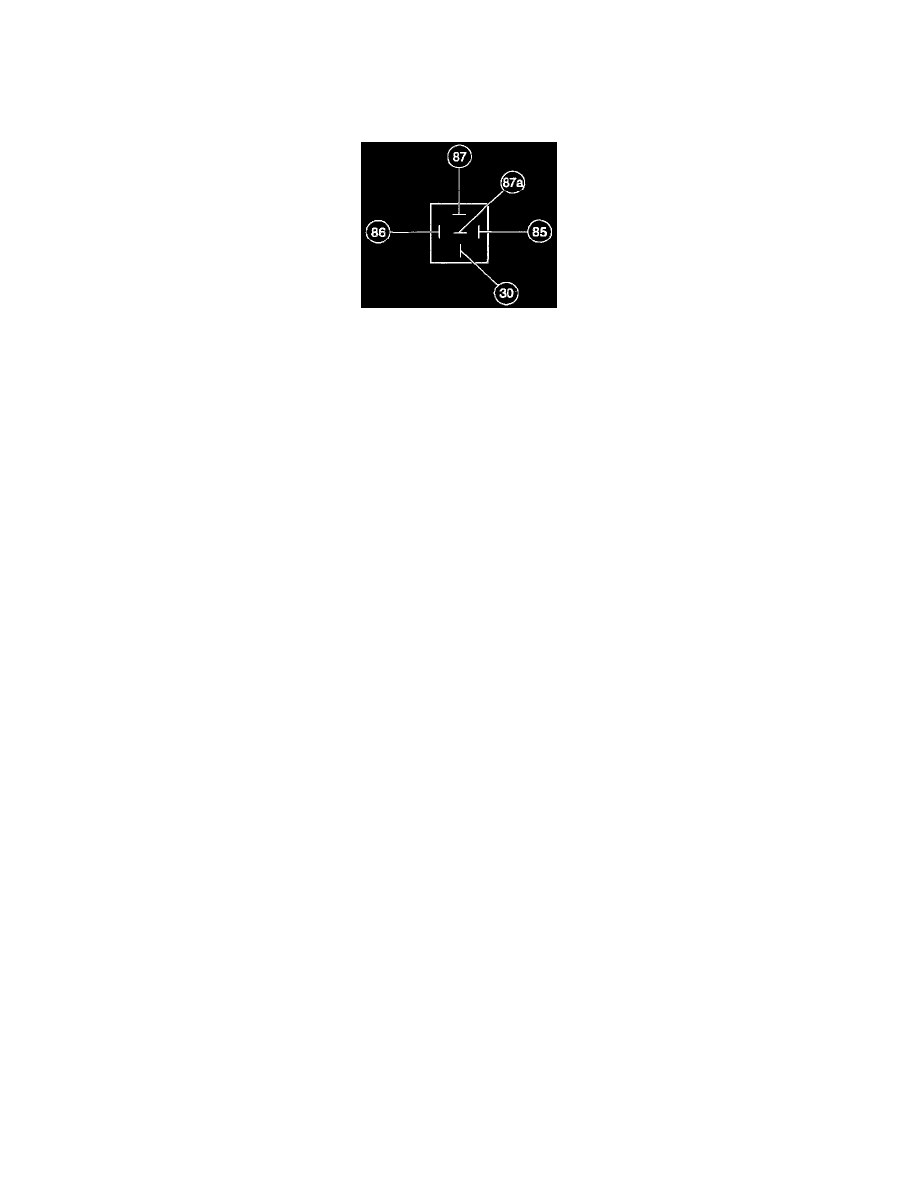
Mini ISO Relay
Use the multimeter to check for the continuity between terminal 85 and all other terminals. If resistance is 5 ohms or less between terminal 85 and
any other terminal, replace the relay. If resistance is greater than 5 ohms, continue with the test. Use two jumper wires to connect relay terminals
86 and 30 directly to the positive battery terminal. With the multimeter set in the volts position, check for voltage at terminal 87A. If battery
voltage is not indicated, replace the relay. If battery voltage is indicated, connect a third jumper wire to terminal 85 and ground the jumper wire to
a known good ground. Check for voltage at terminal 87. If battery voltage is not indicated, replace the relay.