
Explorer 2WD V6-245 4.0L SOHC VIN E EFI (1997)
^
If the vehicle pulls when the pump motor begins to run, the front sensor opposite the direction of the pull is suspect. Pressing harder on the
pedal once the pump motor turns on should cause the steering wheel to veer further in the direction of the pull.
^
If pulsation is present without a significant pull, the rear sensor is suspect.
^
To confirm the vehicle pull is a result of the ABS, disable the ABS by removing the fuse (14) and re-evaluate. If the pull is still present, use the
Vehicle Pulls While Braking symptom (refer to the appropriate Explorer/Mountaineer Workshop Manual, Section 204-00) to diagnose and
correct the problem before restarting this procedure.
2.
Use New Generation Star (NGS) Tester to determine if ABS diagnostic codes are present. For each code found, follow the Workshop Manual
Pinpoint Test and recommended repair procedure. If the Pinpoint Test leads to sensor replacement, read entire article for important service tips.
Verify the repair by repeating Step 1. If no codes are present or Pinpoint Test(s) lead to "NO PROBLEM FOUND," then continue then Step 3.
3.
Inspect the system components for any obvious signs of damage. Closely inspect the wiring for signs of wear and potential shorts. If sensor is
damaged, read entire article for important service tips. Repair or replace damaged components and verify the repair by repeating Step 1.
4.
For the sensor identified in Step 1, remove sensor and inspect the sensor indicator (tone ring) for any damage or missing teeth. Rotate wheel or
axle to ensure all teeth are checked.
5.
If sensor indicator is damaged, replace and proceed to next Step.
CAUTION
PLUGGING THE SENSOR HOLE IS CRITICAL. DAMAGE TO THE WHEEL BEARING INSIDE WILL OCCUR IF DEBRIS FROM THE
CLEANING OPERATION SHOULD HAPPEN TO FALL IN THE HOLE.
6.
Plug the hub assembly opening for the sensor to keep it free of debris. Thoroughly clean the hub mating surface using fine grade sand paper or a
wire brush to make certain it is completely free of all corrosion.
7.
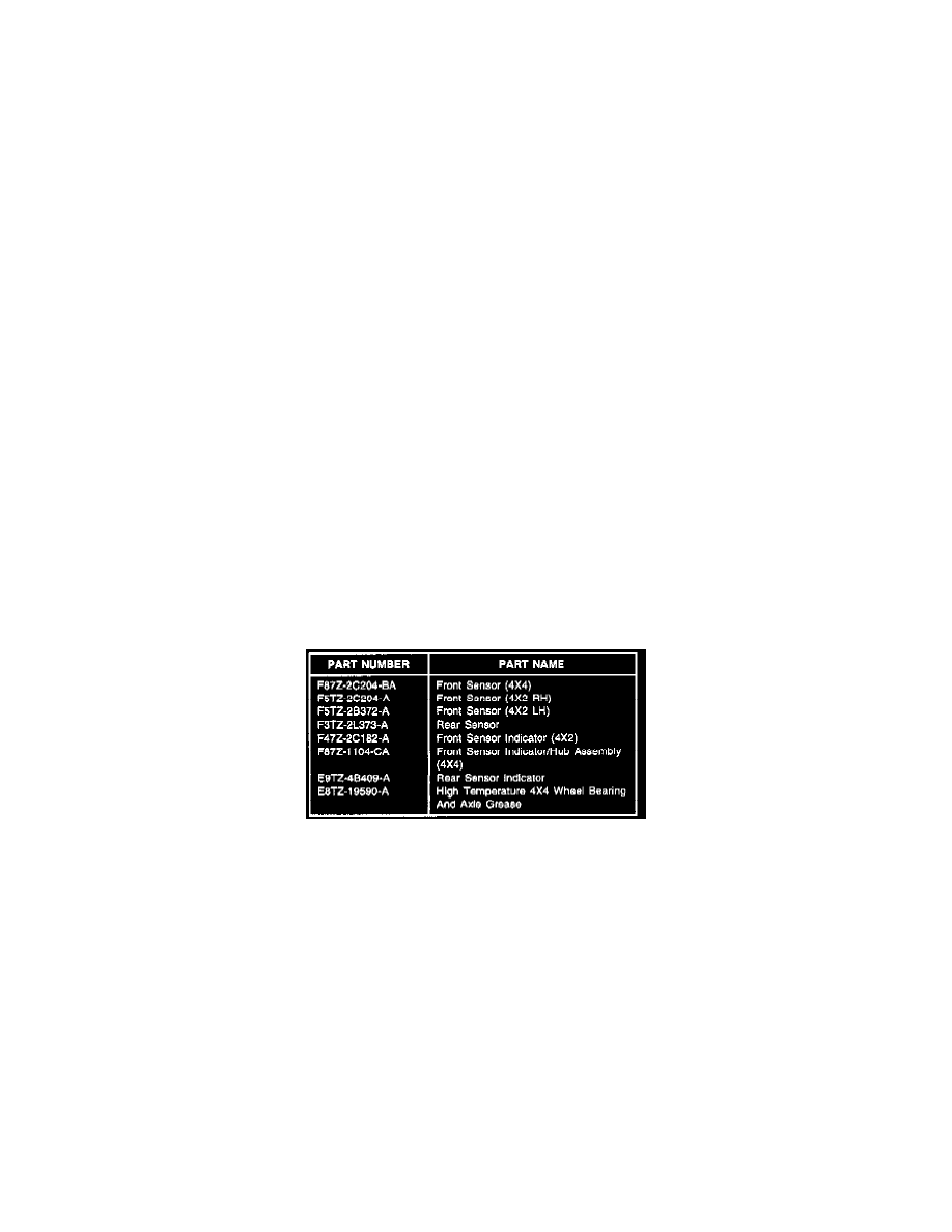
For front sensors, apply a conservative layer of High Temperature 4X4 Wheel Bearing And Axle Grease (E8TZ-19590-A, or equivalent meeting
Ford specification ESA-MIC198-A) between the ABS sensor body and the machined pad on the bearing forging to prevent future corrosion. Be
careful to keep the sensor opening and the sensor indicator free of grease.
8.
If sensor indicator was replaced in Step 5, reinstall sensor and verify the repair by repeating Step 1.
9.
If sensor indicator was not damaged or replacing indicator failed to correct the problem, replace sensor with recommended service part reference
in the Parts Block at the end of this article, and verify repair by repeating Step 1.
NOTE
THE 1998 4X4 FRONT SENSOR HAS A STRONGER SIGNAL THAN PREVIOUS RELEASE. FOR PROPER OPERATION, THE SENSORS
MUST HAVE MATCHING LEVELS. REPLACE OPPOSITE FRONT WHEEL SENSOR ON 1995-97 4X4 MODELS ASSUMING IT IS THE
PRIOR LEVEL.
10.
If problem still exists, one of the following is most likely:
^
the sensor indicator is damaged or defective
^
installation of the new sensor was not properly performed
^
another sensor signal is weak
11.
Verify the installation making certain the indicator and sensor head are free of grease. If installation is correct, replace the hub assembly and install
new indicator in the side identified in Step 1. Verify the repair by repeating Step 1.
12.
If problem still exists, replace other sensors following the recommendations outlined in this article.