
Explorer 2WD V6-245 4.0L VIN X SFI (1999)
3. Position the main control valve body with the two Valve Body Guide Pins as a guide.
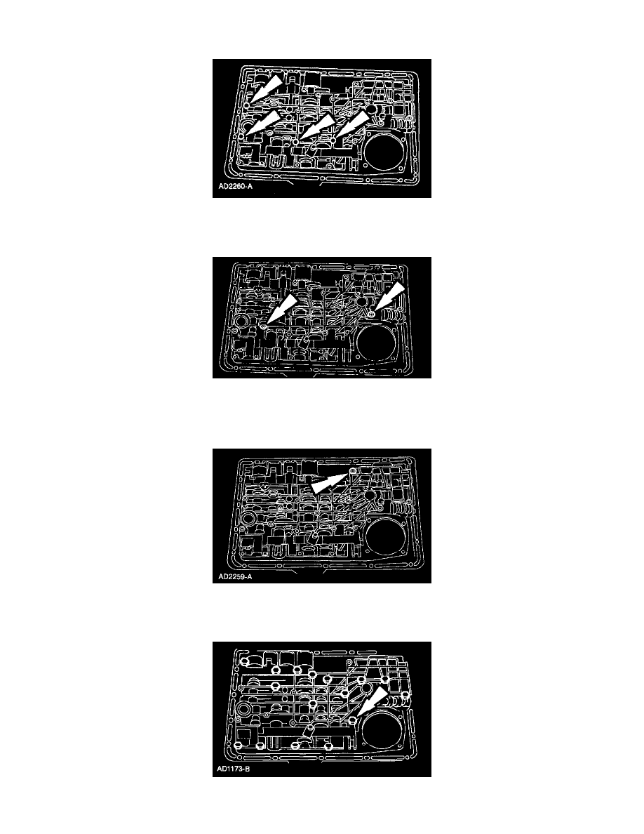
4. NOTE: The main control valve body screws will be tightened in later steps.
Loosely install four M6 x 45 mm screws.
5. NOTE: The main control valve body screws will be tightened in later steps.
Loosely install two M6 x 35 mm screws.
6. Remove the Valve Body Guide Pins.
7. NOTE: The main control valve body screws will be tightened in later steps.
Loosely install the M6 x 30 mm screw.
8. NOTE: The main control valve body screws will be tightened in later steps.