
Explorer 2WD V6-4.0L (2009)
Brake Lamp: Initial Inspection and Diagnostic Overview
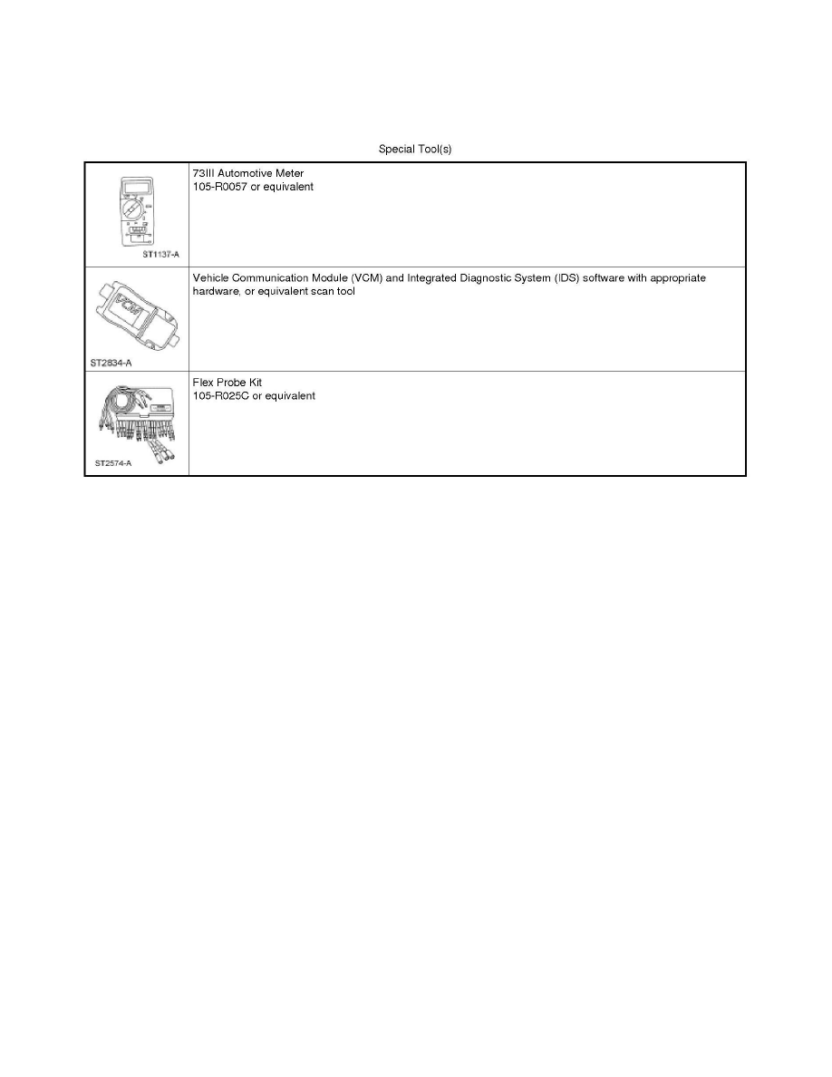
Special Tools Used With Diagnostics
Stoplamps
Principles Of Operation
Stoplamps
Principles of Operation
NOTE: The Smart Junction Box (SJB) is also known as the Generic Electronic Module (GEM).
The SJB monitors the input from the stoplamp switch. When the brake pedal is applied, voltage is routed to the SJB. The SJB then supplies voltage to
the stoplamps.
Field-Effect Transistor (FET) Protection
The SJB utilizes a Field-Effect Transistor (FET) protective circuit strategy for many of its outputs (for example, a headlamp output circuit). Output loads
(current level) are monitored for excessive current (typically short circuits) and are shut down (turns off the voltage or ground provided by the module)
when a fault event is detected. A continuous DTC is stored at the fault event and a cumulative counter is started.
When the demand for the output is no longer present, the module resets the FET circuit protection to allow the circuit to function. The next time the
driver requests a circuit to activate that has been shut down by a previous short (FET protection) and the circuit remains shorted, the FET protection
shuts off the circuit again and the cumulative counter advances.
When the excessive circuit load occurs often enough, the module shuts down the output until a repair procedure is carried out. Each FET protected
circuit has 3 predefined levels of short circuit tolerance based on the harmful effect of each circuit fault on the FET and the ability of the FET to
withstand it. A module lifetime level of fault events is established based upon the durability of the FET. If the total tolerance level is determined to be
600 fault events, the 3 predefined levels would be 200, 400 and 600 fault events.
When each tolerance level is reached, the continuous DTC that was stored on the first failure cannot be cleared by a command to clear the continuous
DTCs. The module does not allow this code to be cleared or the circuit restored to normal operation until a successful self-test proves that the fault has
been repaired. After the self-test has successfully completed (no on-demand DTCs present), the continuous DTC automatically clears and the circuit
function returns.
When the first or second level is reached, the continuous DTC (associated with the short circuit) sets along with DTC B106E. These DTCs can be
cleared using the module on-demand self-test, then the Clear DTC operation on the scan tool (if the on-demand test shows the fault corrected). The
module never resets the fault event counter to zero and continues to advance the fault event counter as short circuit fault events occur.