
Explorer 2WD V6-4.0L (2009)
Brake Lamp: Pinpoint Tests
Pinpoint Test I: One Or More Stoplamps Are Inoperative
Stoplamps
Pinpoint Tests
Pinpoint Test I: One Or More Stoplamps Are Inoperative
Refer to Wiring Diagram Set 90, Turn Signal/Stop/Hazard Lamps for schematic and connector information. See: Diagrams/Electrical
Diagrams/Diagrams By Number
Normal Operation - All Vehicles
When the brake pedal is applied, the stoplamp switch routes voltage to the Smart Junction Box (SJB). The voltage is then routed out of the SJB to the
high mounted stoplamp through circuit CCB08 (VT/WH).
Explorer
When the SJB detects the brake pedal is applied, the SJB provides voltage to the LH and RH rear stoplamps through circuits CLS18 (GY/BN) and
CLS19 (VT/OG). Ground for the high mounted stoplamp and the LH rear stoplamp is provided through circuit GD149 (BK/GY). Ground for the RH
rear stoplamp is provided through circuit GD151 (BK/GN).
Explorer Sport Trac
When the SJB detects the brake pedal is applied, the SJB provides voltage to the LH and RH rear stoplamps through circuits CLS18 (GY/BN) and
CLS19 (VT/OG). Ground for the high mounted stoplamp is provided through circuit GD133 (BK). Ground for the LH and RH rear stoplamps is
provided through circuit GD148 (BK/YE).
Mountaineer
When the SJB detects the brake pedal is applied, the SJB provides voltage to the LH and RH rear stoplamps through circuit CLS44 (VT/BN). Ground
for the high mounted stoplamp and the LH rear stoplamp is provided through circuit GD149 (BK/GY). Ground for the RH rear stoplamp is provided
through circuit GD151 (BK/GN).
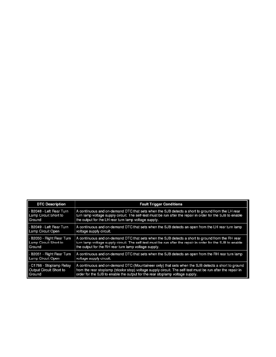
B2048-B2051 / C1788
This pinpoint test is intended to diagnose the following:
-
Fuse
-
Wiring, terminals or connectors
-
High mounted stoplamp
-
LED module
-
SJB
PINPOINT TEST I: ONE OR MORE STOPLAMPS ARE INOPERATIVE