
Explorer 2WD V6-4.0L (2009)
-------------------------------------------------
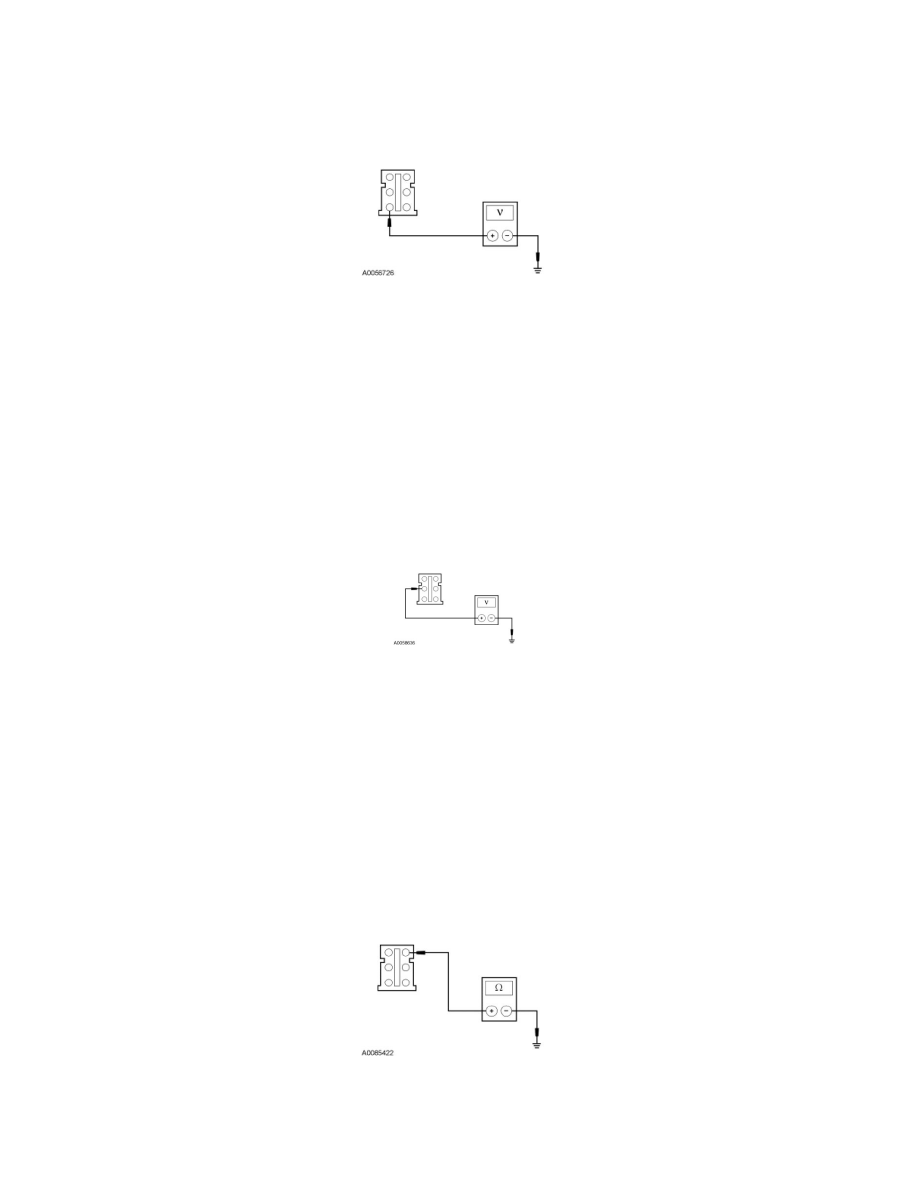
AD3 CHECK CIRCUIT SBB17 (RD) FOR AN OPEN
-
Disconnect: C238.
-
Measure the voltage between the TBC module C238-1, circuit SBB17 (RD), harness side and ground.
-
Is the voltage greater than 10 volts?
Yes
GO to AD4.
No
VERIFY the BJB fuse 17 (30A) is OK. If OK, REPAIR the circuit. TEST the system for normal operation. If not OK, REFER to the Wiring Diagrams to
identify the possible causes of the circuit short.
-------------------------------------------------
AD4 CHECK CIRCUIT CCB08 (VT/WH) FOR AN OPEN
-
While applying the brake pedal, measure the voltage between the TBC module C238-2, circuit CCB08 (VT/WH), harness side and ground.
-
Is the voltage greater than 10 volts?
Yes
GO to AD5.
No
REPAIR the circuit. TEST the system for normal operation.
-------------------------------------------------
AD5 CHECK CIRCUIT GD138 (BK/WH) FOR AN OPEN
-
Disconnect: Negative Battery Cable.
-
Measure the resistance between the TBC module C238-6, circuit GD138 (BK/WH), harness side and ground.
-
Is the resistance less than 5 ohms?
Yes