
Explorer 2WD V6-4.0L (2009)
-
Deactivate the SRS. Refer to Air Bag Systems.
-
Repower the SRS. Refer to Air Bag Systems.
-
Ignition ON.
-
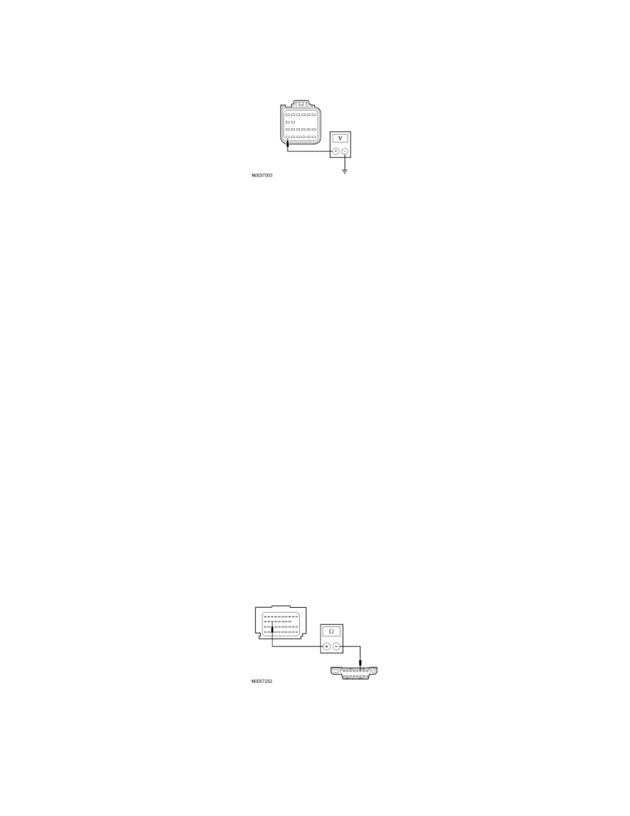
Measure the voltage between the RCM C310a-24, circuit CBP17 (BN/GN), harness side and ground.
-
Is the voltage greater than 10 volts?
Yes
GO to D3.
No
VERIFY the Smart Junction Box (SJB) fuse 17 (10A) is OK. If OK, REPAIR the circuit. If not OK, REFER to the Wiring Diagrams to identify the
possible causes of the circuit short.
REACTIVATE the SRS. REFER to Air Bag Systems. CLEAR the DTCs. REPEAT the network test with the scan tool.
-------------------------------------------------
D3 CHECK THE RCM CASE GROUND
-
Ignition OFF.
-
Disconnect: Negative Battery Cable.
-
Measure the resistance between the RCM case and a good chassis ground.
-
Is the resistance less than 5 ohms?
Yes
GO to D4.
No
REPAIR the RCM case ground as necessary. CONNECT the negative battery cable. REACTIVATE the SRS. REFER to Air Bag Systems. CLEAR the
DTCs. REPEAT the network test with the scan tool.
-------------------------------------------------
D4 CHECK THE HS-CAN CIRCUITS BETWEEN THE RCM AND THE DLC FOR AN OPEN
-
Measure the resistance between the RCM C310b-18, circuit VDB04 (WH/BU), harness side and the DLC C251-6, circuit VDB04 (WH/BU),
harness side.
-
Measure the resistance between the RCM C310b-17, circuit VDB05 (WH), harness side and the DLC C251-14, circuit VDB05 (WH), harness
side.